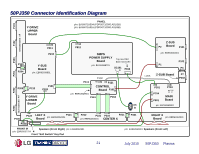
LG 50PJ340 Training Manual - Page 23
Disassembly Procedure for Circuit Board Removal (2
 |
View all LG 50PJ340 manuals
Add to My Manuals
Save this manual to your list of manuals |
Page 23 highlights
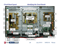
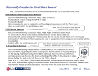
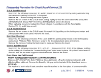
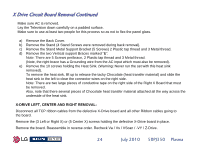
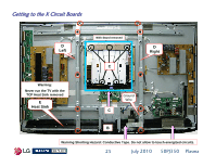
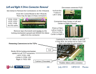
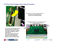
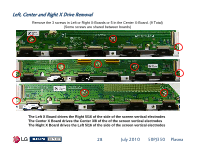
Disassembly Procedure for Circuit Board Removal (2) Z-SUS Board Removal Disconnect the following connectors: P1 and P2, then P101, P102 and P202 by pulling out the locking mechanism and pulling out the FPC to the panel. Remove the 11 screws holding the board in place. Remove the two screws in the Z-SUB board. Lift up slightly to clear the screw stand-offs and pull the Z-SUS to the left. Unseat P3/P7 from the Z-SUB board and remove the board. When replacing, be sure to readjust the Va/Vs voltages in accordance with the Panel Label. Confirm VS, -Vy and Z-bias as well. Z-SUB Board Removal Remove the two screws in the Z-SUB board. Remove P202 by pulling out the locking mechanism and pulling out the FPC to the panel. Remove the board. Main Board Removal Disconnect the following connectors: P703 LVDS and P301 (press gently inward on the locking tabs) and pull out, P704 and P801. Remove 1 screw in the decorative plastic piece and remove. Remove the 4 screws holding the Main board in place and Remove the board. Control Board Removal Disconnect the following connectors: P12 LVDS, P111 Ribbon and P101, P102, P104 Ribbons by lifting up the locking tab. Remove the 2 screws holding the Control board in place. Lift up the Control board to unseat it from the two metal supports at the bottom and Remove the board. Front IR and Key Pad Removal FRONT IR/INTELLIGENT SENSOR and POWER BUTTON: Disconnect P100 and P101. Note: P101 is a ribbon connector. Lift up the locking mechanism and slide the ribbon cable out. Remove the Board by lifting up on the top tabs, lift the board and remove. KEY PAD: The Key Pad is a thin strip of static sensitive material attached to the front glass. It is not removable. 23 July 2010 50PJ350 Plasma
-
 1
1 -
2
-
3
-
4
-
5
-
6
-
7
-
8
-
9
-
10
-
11
-
12
-
13
-
14
-
15
-
16
-
17
-
 18
18 -
 19
19 -
 20
20 -
 21
21 -
 22
22 -
 23
23 -
 24
24 -
 25
25 -
 26
26 -
 27
27 -
 28
28 -
29
-
30
-
31
-
32
-
33
-
34
-
35
-
36
-
37
-
38
-
39
-
40
-
41
-
42
-
43
-
44
-
45
-
46
-
47
-
48
-
49
-
50
-
51
-
52
-
53
-
54
-
55
-
56
-
57
-
58
-
59
-
60
-
61
-
62
-
63
-
64
-
65
-
66
-
67
-
68
-
69
-
70
-
71
-
72
-
73
-
74
-
75
-
76
-
77
-
78
-
79
-
80
-
81
-
82
-
83
-
84
-
85
-
86
-
87
-
88
-
89
-
90
-
91
-
92
-
93
-
94
-
95
-
96
-
97
-
98
-
99
-
100
-
101
-
102
-
103
-
104
-
105
-
106
-
107
-
108
-
109
-
110
-
111
-
112
-
113
-
114
-
115
-
116
-
117
-
118
-
119
-
120
-
121
-
122
-
123
-
124
-
125
-
126
-
127
-
128
-
129
-
130
-
131
-
132
-
133
 |
 |
