LG 50PJ340 Training Manual - Page 43
SMPS Connector SC101 and P812 Identification, Voltages and Diode Check
 |
View all LG 50PJ340 manuals
Add to My Manuals
Save this manual to your list of manuals |
Page 43 highlights
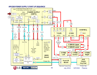
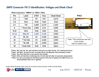
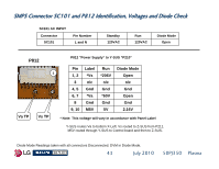
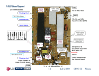
SMPS Connector SC101 and P812 Identification, Voltages and Diode Check SC101 AC INPUT Connector SC101 Pin Number L and N Standby 120VAC Run 120VAC Diode Mode Open P812 P812 "Power Supply" to Y-SUS "P210" Va TP 1 Vs TP Pin 1, 2 3 4, 5 6, 7 8 9, 10 Label *Vs n/c Gnd *Va Gnd M5V Run *206V n/c Gnd *60V Gnd 5V Diode Mode Open n/c Gnd Open Gnd 2.16V * Note: This voltage will vary in accordance with Panel Label Y-SUS routes Va to bottom X-Left. Vs routed to Z-SUS from P211. M5V routed through Y-SUS to Control board and then to Z-SUS. Diode Mode Readings taken with all connectors Disconnected. DVM in Diode Mode. 43 July 2010 50PJ350 Plasma
-
 1
1 -
2
-
3
-
4
-
5
-
6
-
7
-
8
-
9
-
10
-
11
-
12
-
13
-
14
-
15
-
16
-
17
-
18
-
19
-
20
-
21
-
22
-
23
-
24
-
25
-
26
-
27
-
28
-
29
-
30
-
31
-
32
-
33
-
34
-
35
-
36
-
37
-
 38
38 -
 39
39 -
 40
40 -
 41
41 -
 42
42 -
 43
43 -
 44
44 -
 45
45 -
 46
46 -
 47
47 -
 48
48 -
49
-
50
-
51
-
52
-
53
-
54
-
55
-
56
-
57
-
58
-
59
-
60
-
61
-
62
-
63
-
64
-
65
-
66
-
67
-
68
-
69
-
70
-
71
-
72
-
73
-
74
-
75
-
76
-
77
-
78
-
79
-
80
-
81
-
82
-
83
-
84
-
85
-
86
-
87
-
88
-
89
-
90
-
91
-
92
-
93
-
94
-
95
-
96
-
97
-
98
-
99
-
100
-
101
-
102
-
103
-
104
-
105
-
106
-
107
-
108
-
109
-
110
-
111
-
112
-
113
-
114
-
115
-
116
-
117
-
118
-
119
-
120
-
121
-
122
-
123
-
124
-
125
-
126
-
127
-
128
-
129
-
130
-
131
-
132
-
133
 |
 |

43
July 2010
50PJ350
Plasma
SMPS Connector SC101 and P812 Identification, Voltages and Diode
SMPS Connector SC101 and P812 Identification, Voltages and Diode
Check
Check
2.16V
5V
M5V
9, 10
Gnd
Gnd
Gnd
8
Open
*60V
*Va
6, 7
Gnd
Gnd
Gnd
4, 5
n/c
n/c
n/c
3
Open
*206V
*Vs
1, 2
Diode Mode
Run
Label
Pin
SC101 AC INPUT
Standby
Run
Diode Mode
Connector
Pin Number
SC101
120VAC
120VAC
Open
L and N
Diode Mode Readings taken with all connectors Disconnected. DVM in Diode Mode.
P812 "Power Supply“ to Y-SUS “P210”
* Note: This voltage will vary in accordance with Panel Label
P812
1
Y-SUS routes Va to bottom X-Left. Vs routed to Z-SUS from P211.
M5V routed through Y-SUS to Control board and then to Z-SUS.
Va TP
V
s
TP