LG 50PJ340 Training Manual - Page 44
Y-sus Board
 |
View all LG 50PJ340 manuals
Add to My Manuals
Save this manual to your list of manuals |
Page 44 highlights
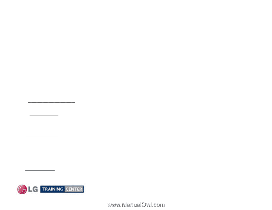
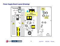
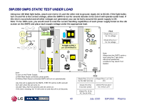
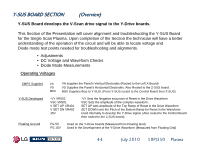
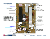
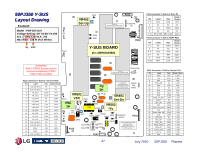
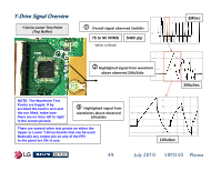
Y-SUS BOARD SECTION (Overview) Y-SUS Board develops the V-Scan drive signal to the Y-Drive boards. This Section of the Presentation will cover alignment and troubleshooting the Y-SUS Board for the Single Scan Plasma. Upon completion of the Section the technician will have a better understanding of the operation of the circuit and will be able to locate voltage and Diode mode test points needed for troubleshooting and alignments. • Adjustments • DC Voltage and Waveform Checks • Diode Mode Measurements Operating Voltages SMPS Supplied Y-SUS Developed Floating Ground VA VS M5V VA supplies the Panel's Vertical Electrodes (Routed to the Left X-Board) VS Supplies the Panel's Horizontal Electrodes. Also Routed to the Z-SUS board. M5V Supplies Bias to Y-SUS. (From Y-SUS routed to the Control Board then Z-SUS). -VY VR502 VSC VR501 V SET UP VR401 V SET DN VR402 16V -VY Sets the Negative excursion of Reset in the Drive Waveform VSC Sets the amplitude of the complex waveform. SET UP sets amplitude of the Top Ramp of Reset in the Drive Waveform SET DOWN sets the Pitch of the Bottom Ramp for Reset in the Waveform Used internally to develop the Y-Drive signal. (Also routed to the Control Board then routed to the Z-SUS board). FG 5V FG 15V Used on the Y-Drive boards (Measured from Floating Gnd) Used in the Development of the Y-Drive Waveform (Measured from Floating Gnd) 44 July 2010 50PJ350 Plasma
-
 1
1 -
2
-
3
-
4
-
5
-
6
-
7
-
8
-
9
-
10
-
11
-
12
-
13
-
14
-
15
-
16
-
17
-
18
-
19
-
20
-
21
-
22
-
23
-
24
-
25
-
26
-
27
-
28
-
29
-
30
-
31
-
32
-
33
-
34
-
35
-
36
-
37
-
38
-
 39
39 -
 40
40 -
 41
41 -
 42
42 -
 43
43 -
 44
44 -
 45
45 -
 46
46 -
 47
47 -
 48
48 -
 49
49 -
50
-
51
-
52
-
53
-
54
-
55
-
56
-
57
-
58
-
59
-
60
-
61
-
62
-
63
-
64
-
65
-
66
-
67
-
68
-
69
-
70
-
71
-
72
-
73
-
74
-
75
-
76
-
77
-
78
-
79
-
80
-
81
-
82
-
83
-
84
-
85
-
86
-
87
-
88
-
89
-
90
-
91
-
92
-
93
-
94
-
95
-
96
-
97
-
98
-
99
-
100
-
101
-
102
-
103
-
104
-
105
-
106
-
107
-
108
-
109
-
110
-
111
-
112
-
113
-
114
-
115
-
116
-
117
-
118
-
119
-
120
-
121
-
122
-
123
-
124
-
125
-
126
-
127
-
128
-
129
-
130
-
131
-
132
-
133
 |
 |