LG 50PJ340 Training Manual - Page 85
Control Board Component Identification and Checks, IC231, Auto Gen, D201 LED, PANEL TEST
 |
View all LG 50PJ340 manuals
Add to My Manuals
Save this manual to your list of manuals |
Page 85 highlights
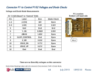
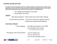
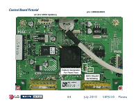
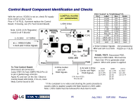
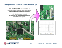
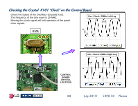
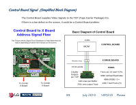
Control Board Component Identification and Checks With the unit on, if D201 is not on, check 5V supply from FS202 on the Y-SUS. Pins 4~7 of P111. If present replace the Control Board. If missing, see (To Test Control Board) Note: IC231 (3.3V Regulator) routed to all X Boards 1~3 (16V) 4-7 (M5V) Ribbon Cable Y-SUS and Y Drive Signals P102 IC231 P111 IC101 IC801 P161 CONTROL BOARD p/n: EBR63549501 LVDS Video P121 X101 IC141 IC211 IC101 IC1 Auto Gen P101 VS_DA D201 LED P162 P101 "Control" to "Z-SUS Board" P1 Pin Label Run Diode 1 (+15V) 16V Open 2 (+15V) 16V Open 3 (+5V) 4.9V 1.52V 4 (+5V) 4.9V 1.52V 5 Gnd Gnd Gnd 6 Y_OE 0.058V 3.09V 7 ZBIAS 1.83V Open 8 Slop_Ctl Gnd Open 9 Z_ER 0.14V Open 10 ZSUS_DN 0.77V Open 11 ZSUS_UP 0.17V Open 12 Gnd Gnd Gnd Z-Drive Creation Signals 16V protected by M5V and 16V to Z-SUS FS204 on Y-SUS PANEL TEST: Disconnect P301, Remove LVDS Cable. Short across Auto Gen TPs to generate a test pattern. When A/C power is applied. To Test Control Board: Disconnect all connectors. Jump STBY 5V from SMPS P813 Pin 13 to pin 3 (bottom leg) of IC231. X-Drive Center and Left RGB Signals 3.3V and X-Drive Center and Right RGB Signals IC231 (1) Gnd (2) 3.29V (3) 4.94V Apply AC and turn on the Set. Observe Control board LED D201, if it's on, most 3.3V from IC231 Pins 56~60 likely Control board is OK. * If the complaint is no video and shorting the points (AutoGen) causes video to appear suspect the Main board or LVDS cable. Note: LVDS Cable must be removed for Auto Gen to work. IC801 (1) 1.79V (2) 3.29V (3) n/c (4) 0V (5) 0V IC211 (1) Gnd (2) 1.8V (3) 3.27V 85 July 2010 50PJ350 Plasma
-
 1
1 -
2
-
3
-
4
-
5
-
6
-
7
-
8
-
9
-
10
-
11
-
12
-
13
-
14
-
15
-
16
-
17
-
18
-
19
-
20
-
21
-
22
-
23
-
24
-
25
-
26
-
27
-
28
-
29
-
30
-
31
-
32
-
33
-
34
-
35
-
36
-
37
-
38
-
39
-
40
-
41
-
42
-
43
-
44
-
45
-
46
-
47
-
48
-
49
-
50
-
51
-
52
-
53
-
54
-
55
-
56
-
57
-
58
-
59
-
60
-
61
-
62
-
63
-
64
-
65
-
66
-
67
-
68
-
69
-
70
-
71
-
72
-
73
-
74
-
75
-
76
-
77
-
78
-
79
-
 80
80 -
 81
81 -
 82
82 -
 83
83 -
 84
84 -
 85
85 -
 86
86 -
 87
87 -
 88
88 -
 89
89 -
 90
90 -
91
-
92
-
93
-
94
-
95
-
96
-
97
-
98
-
99
-
100
-
101
-
102
-
103
-
104
-
105
-
106
-
107
-
108
-
109
-
110
-
111
-
112
-
113
-
114
-
115
-
116
-
117
-
118
-
119
-
120
-
121
-
122
-
123
-
124
-
125
-
126
-
127
-
128
-
129
-
130
-
131
-
132
-
133
 |
 |
