LG 50PJ340 Training Manual - Page 51
Observing (Capturing) the Y-Drive Signal for Set Up Adjustment
 |
View all LG 50PJ340 manuals
Add to My Manuals
Save this manual to your list of manuals |
Page 51 highlights
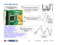
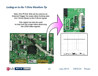
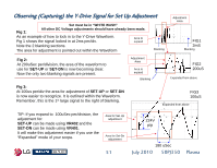
Observing (Capturing) the Y-Drive Signal for Set Up Adjustment Set must be in "WHITE WASH" Fig 1: All other DC Voltage adjustments should have already been made. As an example of how to lock in to the Y-Drive Waveform. Fig 1 shows the signal locked in at 2ms per/div. Area to expand Note the 2 blanking sections. The area for adjustment is pointed out within the Waveform Blanking Adjustment Area FIG1 2mS Blanking Fig 2: At 200uSec per/division, the area of the waveform to use for SET-UP or SET-DN is now becoming clear. Now the only two blanking signals are present. Adjustment Area Area to expand Blanking FIG2 200uS Expanded from above Fig 3: At 100us per/div the area for adjustment of SET-UP or SET-DN is now easier to recognize. It is outlined within the Waveform. Remember, this is the 1st large signal to the right of blanking. FIG3 100uS Expanded from above TIP: If you expand to 100uSec per/division, the adjustment for: SET-UP can be made using VR402 and the SET-DN can be made using VR401. It will make this adjustment easier if you use the "Expanded" mode of your scope. Area for Set-Up adjustment Area for Set-Dn adjustment 51 224V p/p 180 uSec July 2010 50PJ350 Plasma
-
 1
1 -
2
-
3
-
4
-
5
-
6
-
7
-
8
-
9
-
10
-
11
-
12
-
13
-
14
-
15
-
16
-
17
-
18
-
19
-
20
-
21
-
22
-
23
-
24
-
25
-
26
-
27
-
28
-
29
-
30
-
31
-
32
-
33
-
34
-
35
-
36
-
37
-
38
-
39
-
40
-
41
-
42
-
43
-
44
-
45
-
 46
46 -
 47
47 -
 48
48 -
 49
49 -
 50
50 -
 51
51 -
 52
52 -
 53
53 -
 54
54 -
 55
55 -
 56
56 -
57
-
58
-
59
-
60
-
61
-
62
-
63
-
64
-
65
-
66
-
67
-
68
-
69
-
70
-
71
-
72
-
73
-
74
-
75
-
76
-
77
-
78
-
79
-
80
-
81
-
82
-
83
-
84
-
85
-
86
-
87
-
88
-
89
-
90
-
91
-
92
-
93
-
94
-
95
-
96
-
97
-
98
-
99
-
100
-
101
-
102
-
103
-
104
-
105
-
106
-
107
-
108
-
109
-
110
-
111
-
112
-
113
-
114
-
115
-
116
-
117
-
118
-
119
-
120
-
121
-
122
-
123
-
124
-
125
-
126
-
127
-
128
-
129
-
130
-
131
-
132
-
133
 |
 |
