LG 50PJ340 Training Manual - Page 30
Signal and Voltage Distribution Block Diagram, Y-SUS Board, Board, MAIN Board, X-Board-Right
 |
View all LG 50PJ340 manuals
Add to My Manuals
Save this manual to your list of manuals |
Page 30 highlights
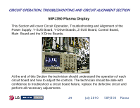
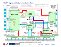
50PJ350 Signal and Voltage Distribution Block Y Drive Upper FPCs 5VFG (5V) measured from Floating Ground 15VFG (15V) measured from Floating Ground SMPS TURN ON SEQUENCE Step 1: RL_ON: 17V, 5V, AC_Det, Error Det, Step 2: M_On: M5V, Va, Vs SMPS OUTPUT VOLTAGES IN STBY STB +5V SMPS OUTPUT VOLTAGES IN RUN STB5V, +5V, 17V to Main Board Vs, Va and M5V to Y-SUS, Display Panel Horizontal Electrodes Sustain P101 P102 P103 FPCs P201 P202 P110 P204 P211 FG P210 FG Y-SUS Board Scan P110 / P204 Floating Gnd (FG) Drive Signals, FG5V and Vscan. FG5V Scan FG15V 16V VSC -VY FG P101 FG P812 M5V, Vs, Va Note: Va not used by Y-SUS only fused and routed to the X-Board SMPS Board SK101 P813 AC Input Filter LVDS Video Logic Signals Display Enable To Y-SUS and Y-Drive 16V / M5V Note: 16V not used by Control P111 P121 CONTROL Board P101 Error Com SMPS Turn On Commands RL_ON Vs 17V, +5V, AC Det Z-SUS Board P2 FPCs P101 M_On M5V, Va, Vs P102 Stand By: STB +5 Run: AC Det +5, 17V 16V / M5V Z Drive Control P1 Signals P3 Z-SUB P7 Board P202 FPCs P203 P205 P212 Y Drive Floating Gnd (FG) Drive Signals, FG5V Lower Display Panel Horizontal Electrodes Reset, Sustain P114 Va P161 P162 3.3V RGB Logic Signals RGB Logic Signals 3.3V STBY 3.3V P231 P232 3.3V 3.3V P301 P703 Speakers MAIN Board P704 P801 3.3V Key Board Pull Up IR, Soft Touch Keys P100 Intelligent Sensor P101 And Power Button X-Board-Left P122 P121 P212 PX23-2BoPa21r1dP3-1C1 eP3n3t1er P211 P331 X-Board-Right Va Va P101 P102 P103 P104 P105 P201 P202 P203 P204 P205 P206 P301 P302 P303 P304 P305 Display Panel Vertical Address (Colored Cell Address) 30 July 2010 50PJ350 Plasma
-
 1
1 -
2
-
3
-
4
-
5
-
6
-
7
-
8
-
9
-
10
-
11
-
12
-
13
-
14
-
15
-
16
-
17
-
18
-
19
-
20
-
21
-
22
-
23
-
24
-
 25
25 -
 26
26 -
 27
27 -
 28
28 -
 29
29 -
 30
30 -
 31
31 -
 32
32 -
 33
33 -
 34
34 -
 35
35 -
36
-
37
-
38
-
39
-
40
-
41
-
42
-
43
-
44
-
45
-
46
-
47
-
48
-
49
-
50
-
51
-
52
-
53
-
54
-
55
-
56
-
57
-
58
-
59
-
60
-
61
-
62
-
63
-
64
-
65
-
66
-
67
-
68
-
69
-
70
-
71
-
72
-
73
-
74
-
75
-
76
-
77
-
78
-
79
-
80
-
81
-
82
-
83
-
84
-
85
-
86
-
87
-
88
-
89
-
90
-
91
-
92
-
93
-
94
-
95
-
96
-
97
-
98
-
99
-
100
-
101
-
102
-
103
-
104
-
105
-
106
-
107
-
108
-
109
-
110
-
111
-
112
-
113
-
114
-
115
-
116
-
117
-
118
-
119
-
120
-
121
-
122
-
123
-
124
-
125
-
126
-
127
-
128
-
129
-
130
-
131
-
132
-
133
 |
 |
