Lexmark E260dn Service Manual - Page 75
LVPS/HVPS service check, Main motor service check
 |
View all Lexmark E260dn manuals
Add to My Manuals
Save this manual to your list of manuals |
Page 75 highlights
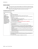
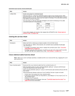
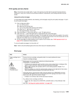
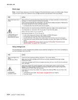
4513-220, -230 LVPS/HVPS service check FRU LVPS/HVPS Action LVPS portion of board Fuses that open typically indicate a faulty LVPS/HVPS. Disconnect the power cable, and open the LVPS/HVPS enough to test the switch. The switch will show continuity across the conductors with a meter when the switch is on. If the switch is good, then see "Dead machine service check" on page 2-48 for more diagnostics. HVPS portion of board Problems with the HVPS are exhibited in the print quality. See "Print quality service checks" on page 2-53 for more information. Main motor service check FRU Main motor gear drive Main motor cable LVPS/HVPS Controller board Warning: Do not replace the operator panel and controller board at the same time. Each card contains the printer settings. When either of these cards is new, it obtains the settings from the other card. Settings are lost when both are new and replaced at the same time. Action Turn off the printer, and unplug the main motor cable at J17. Turn on the printer, and check for the following voltages at J17: J17 pins Voltages Pins 1-4, 6 Pins 7-9 Approx. 5 V dc 18 V dc: 24 V dc Verify ground at pin 5 for both the card and cable. • If these voltages are correct, then check the main motor cable for continuity. - Remove the left side cover to access the connector on the motor. - If continuity exists on each wire, then replace the main motor gear drive which includes the motor. - If continuity does not exist on one or more of the wires, then call the next level of support. • If these voltages are not correct, then see "Controller board connector pin values" on page 5-2, or replace the controller board. See "Controller board removal" on page 4-6. Diagnostics information 2-49
-
 1
1 -
2
-
3
-
4
-
5
-
6
-
7
-
8
-
9
-
10
-
11
-
12
-
13
-
14
-
15
-
16
-
17
-
18
-
19
-
20
-
21
-
22
-
23
-
24
-
25
-
26
-
27
-
28
-
29
-
30
-
31
-
32
-
33
-
34
-
35
-
36
-
37
-
38
-
39
-
40
-
41
-
42
-
43
-
44
-
45
-
46
-
47
-
48
-
49
-
50
-
51
-
52
-
53
-
54
-
55
-
56
-
57
-
58
-
59
-
60
-
61
-
62
-
63
-
64
-
65
-
66
-
67
-
68
-
69
-
 70
70 -
 71
71 -
 72
72 -
 73
73 -
 74
74 -
 75
75 -
 76
76 -
 77
77 -
 78
78 -
 79
79 -
 80
80 -
81
-
82
-
83
-
84
-
85
-
86
-
87
-
88
-
89
-
90
-
91
-
92
-
93
-
94
-
95
-
96
-
97
-
98
-
99
-
100
-
101
-
102
-
103
-
104
-
105
-
106
-
107
-
108
-
109
-
110
-
111
-
112
-
113
-
114
-
115
-
116
-
117
-
118
-
119
-
120
-
121
-
122
-
123
-
124
-
125
-
126
-
127
-
128
-
129
-
130
-
131
-
132
-
133
-
134
-
135
-
136
-
137
-
138
-
139
-
140
-
141
-
142
-
143
-
144
-
145
-
146
-
147
-
148
-
149
-
150
-
151
-
152
-
153
-
154
-
155
-
156
-
157
-
158
-
159
-
160
-
161
-
162
-
163
-
164
-
165
-
166
-
167
-
168
-
169
-
170
-
171
-
172
-
173
-
174
-
175
-
176
 |
 |
