Netgear R6300 R6300 User Manual (PDF) - Page 10
Back Panel, WiFi On/Off button, WPS button - firmware
 |
View all Netgear R6300 manuals
Add to My Manuals
Save this manual to your list of manuals |
Page 10 highlights
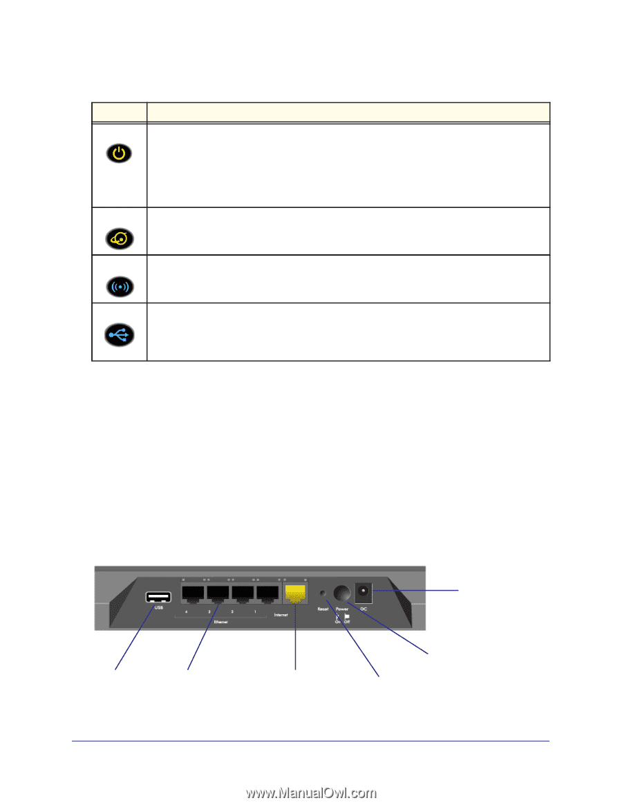
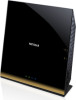
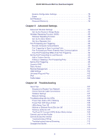
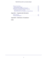
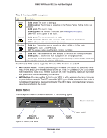
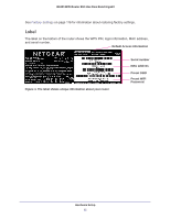
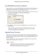
R6300 WiFi Router 802.11ac Dual Band Gigabit Table 1. Front panel LED descriptions LED Description Power • Solid amber. The router is starting up. • Blinking amber. The firmware is upgrading, or the Restore Factory Settings button was pressed. • Solid green. The router is ready. • Blinking green. The firmware is corrupted. See www.netgear.com/support. • Off. Power is not supplied to the router. Internet • Solid green. The Internet connection is ready. • Solid amber. The Ethernet cable connection to the modem has been detected. • Off. No Ethernet cable is connected to the modem. Wireless • Solid blue. The wireless radio is operating in either 2.4 GHz or 5 GHz mode. • Blinking: The router is in WPS mode. • Off. The wireless radios are off for both 2.4 GHz and 5 GHz. USB • Solid blue: The USB device has been accepted by the router and is ready to be used. • Blinking blue: A second USB HDD is plugged in and is trying to connect. • Off: No USB device is connected, someone clicked the Safely Remove Hardware button and it is now safe to remove the attached USB device. The WiFi and WPS buttons toggle the WiFi and WPS functions on and off. • WiFi On/Off button. Pressing and holding the wireless LAN button for 2 seconds turns the 2.4 GHz and 5 GHz wireless radios on and off. If the 2.4 GHz and 5 GHz LEDs are lit, then the wireless radio is on. If these LEDs are off, then the wireless radios are turned off and you cannot connect wirelessly to the router. • WPS button. You can use this button to use WPS to add a wireless device or computer to your wireless network. The LED below the WPS button blinks green when the router is trying to add the wireless device or computer. The LED stays solid green when wireless security is enabled in the router. Back Panel The back panel has the connections shown in the following figure. Power connector USB port Ethernet LAN ports 1-4 Figure 3. Router, rear view Internet port Reset button Power On/Off Hardware Setup 10
-
 1
1 -
2
-
3
-
4
-
 5
5 -
 6
6 -
 7
7 -
 8
8 -
 9
9 -
 10
10 -
 11
11 -
 12
12 -
 13
13 -
 14
14 -
 15
15 -
16
-
17
-
18
-
19
-
20
-
21
-
22
-
23
-
24
-
25
-
26
-
27
-
28
-
29
-
30
-
31
-
32
-
33
-
34
-
35
-
36
-
37
-
38
-
39
-
40
-
41
-
42
-
43
-
44
-
45
-
46
-
47
-
48
-
49
-
50
-
51
-
52
-
53
-
54
-
55
-
56
-
57
-
58
-
59
-
60
-
61
-
62
-
63
-
64
-
65
-
66
-
67
-
68
-
69
-
70
-
71
-
72
-
73
-
74
-
75
-
76
-
77
-
78
-
79
-
80
-
81
-
82
-
83
-
84
-
85
-
86
-
87
-
88
-
89
-
90
-
91
-
92
-
93
-
94
-
95
-
96
-
97
-
98
-
99
-
100
-
101
-
102
-
103
-
104
-
105
-
106
-
107
-
108
-
109
-
110
-
111
-
112
-
113
-
114
-
115
-
116
-
117
-
118
-
119
-
120
-
121
-
122
-
123
-
124
-
125
-
126
-
127
-
128
 |
 |