Pioneer VSX-820-K Owner's Manual - Page 19
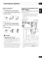
Connect the surround back or front height speakers, Loosen terminal and insert exposed wire. - subwoofer connection
 |
UPC - 884938109277
View all Pioneer VSX-820-K manuals
Add to My Manuals
Save this manual to your list of manuals |
Page 19 highlights
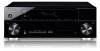
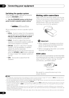
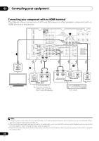
English Deutsch Français Italiano Nederlands Español Connecting your equipment 03 Bare wire connections A-Speaker terminals: 1 Twist exposed wire strands together. 2 Loosen terminal and insert exposed wire. 3 Tighten terminal. 1 2 3 10 mm (3/8 in.) B-Speaker terminals: 1 Twist exposed wire strands together. 2 Push open the tabs and insert exposed wire. 3 Release the tabs. 1 2 3 10 mm (3/8 in.) CAUTION • These speaker terminals carry HAZARDOUS LIVE voltage. To prevent the risk of electric shock when connecting or disconnecting the speaker cables, disconnect the power cord before touching any uninsulated parts. • Make sure that all the bare speaker wire is twisted together and inserted fully into the speaker terminal. If any of the bare speaker wire touches the back panel it may cause the power to cut off as a safety measure. Connect the surround back or front height speakers Connect the PRE OUT outputs of the unit and additional amplifier to add a surround back or front height speaker. • If the surround back speaker or the front height speaker is connected, set the Pre Out setting (see The Pre Out Setting on page 47). Surround back or front height speakers SBL/FHL SBR/FHR Surround back or front height channel amplifier ANALOG INPUT L R IN BD SUBWOOFER PRE OUT CD-R/TAPE DVR/VCR SURR BACK / ADAPTER FRONT DVD HEIGHT (OUTPUT 5 V 1 L (Single) OUT TV/SAT R PRE OUT CD CD-R/TAPE DVR/VCR L COAXIAL ASSIGNABLE DVR/VCR IN 1 (CD) OPTICAL IN 2 OUT IN 1 (CD-R/TAPE) HDMI ASSIGNABLE 12 IN R TV/SAT DVD L IN R AUDIO IN M ANTENNA BD FM UNBAL 75 SIRIUS IN IN AM LOOP • You can use the additional amplifier on the surround back channel pre-outs for a single speaker as well. In this case plug the amplifier into the left (L (Single)) terminal only. 19 En
-
 1
1 -
2
-
3
-
4
-
5
-
6
-
7
-
8
-
9
-
10
-
11
-
12
-
13
-
 14
14 -
 15
15 -
 16
16 -
 17
17 -
 18
18 -
 19
19 -
 20
20 -
 21
21 -
 22
22 -
 23
23 -
 24
24 -
25
-
26
-
27
-
28
-
29
-
30
-
31
-
32
-
33
-
34
-
35
-
36
-
37
-
38
-
39
-
40
-
41
-
42
-
43
-
44
-
45
-
46
-
47
-
48
-
49
-
50
-
51
-
52
-
53
-
54
-
55
-
56
-
57
-
58
-
59
-
60
-
61
-
62
-
63
-
64
-
65
-
66
-
67
-
68
-
69
-
70
-
71
-
72
-
73
-
74
-
75
-
76
-
77
-
78
-
79
-
80
-
81
-
82
-
83
-
84
-
85
-
86
-
87
-
88
-
89
-
90
-
91
-
92
-
93
-
94
-
95
-
96
-
97
-
98
-
99
-
100
-
101
-
102
-
103
-
104
-
105
-
106
-
107
-
108
-
109
-
110
-
111
-
112
-
113
-
114
-
115
-
116
-
117
-
118
-
119
-
120
-
121
-
122
-
123
-
124
-
125
-
126
-
127
-
128
-
129
-
130
-
131
-
132
-
133
-
134
-
135
-
136
-
137
-
138
-
139
-
140
-
141
-
142
-
143
-
144
-
145
-
146
-
147
-
148
-
149
-
150
-
151
-
152
-
153
-
154
-
155
-
156
-
157
-
158
-
159
-
160
-
161
-
162
-
163
-
164
-
165
-
166
-
167
-
168
-
169
-
170
-
171
-
172
-
173
-
174
-
175
-
176
-
177
-
178
-
179
-
180
-
181
-
182
-
183
-
184
-
185
-
186
-
187
-
188
-
189
-
190
-
191
-
192
-
193
-
194
-
195
-
196
-
197
-
198
-
199
-
200
-
201
-
202
-
203
-
204
-
205
-
206
-
207
-
208
-
209
-
210
-
211
-
212
-
213
-
214
-
215
-
216
-
217
-
218
-
219
-
220
-
221
-
222
-
223
-
224
-
225
-
226
-
227
-
228
 |
 |