Sony KDS-R60XBR1 Operating Instructions - Page 17
Front Connectors, Memory Stick, indicator, i.LINK, S VIDEO, LMONO-AUDIO-R - no picture
 |
UPC - 027242681118
View all Sony KDS-R60XBR1 manuals
Add to My Manuals
Save this manual to your list of manuals |
Page 17 highlights
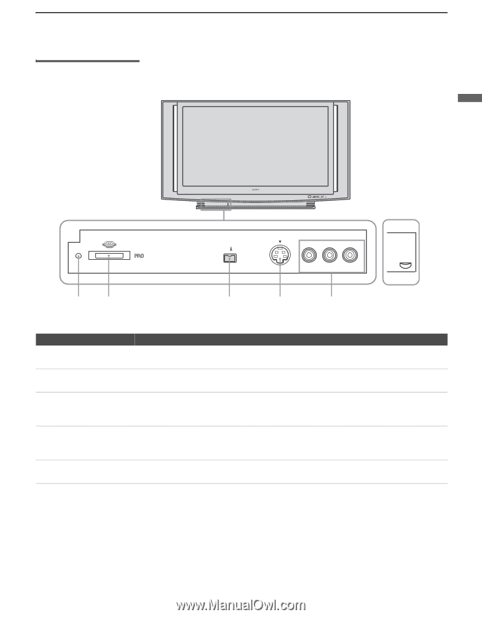
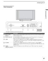
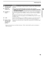
Front Connectors Introducing the TV Introducing the TV STD/DUO POWER/STANDBY LAMP TIMER POWER STD/DUO i.LINK S400 VIDEO 2 INPUT (DV/HDV/MICROMV/TS) S VIDEO VIDEO L(MONO) - AUDIO - R 12 3 Front panel connectors are under the front panel cover 4 5 Push up to open the front panel using the small lip on the panel. Item Description 1 Memory Stick indicator When lit, indicates that the Memory Stick is being read. (Do not remove the Memory Stick when the indicator is lit.) 2 Memory Stick slot For inserting Memory Stick media to view on your TV. For details, See "Inserting and Removing a Memory Stick/Memory Stick Duo" on page 63. 3 i.LINK Connects to the i.LINK jack on your i.LINK-compatible portable device. Provides a secure digital connection between your TV and i.LINK-compatible portable device, such as a digital video camcorder. 4 S VIDEO Connects to the S VIDEO OUT jack of your VCR, camcorder, or other S VIDEOequipped video component. Provides better picture quality than the VHF/UHF jacks or the VIDEO IN jack. 5 VIDEO/ Connects to the audio and video OUT jacks on your VCR or other video component. L(MONO)-AUDIO-R 17
-
 1
1 -
2
-
3
-
4
-
5
-
6
-
7
-
8
-
9
-
10
-
11
-
 12
12 -
 13
13 -
 14
14 -
 15
15 -
 16
16 -
 17
17 -
 18
18 -
 19
19 -
 20
20 -
 21
21 -
 22
22 -
23
-
24
-
25
-
26
-
27
-
28
-
29
-
30
-
31
-
32
-
33
-
34
-
35
-
36
-
37
-
38
-
39
-
40
-
41
-
42
-
43
-
44
-
45
-
46
-
47
-
48
-
49
-
50
-
51
-
52
-
53
-
54
-
55
-
56
-
57
-
58
-
59
-
60
-
61
-
62
-
63
-
64
-
65
-
66
-
67
-
68
-
69
-
70
-
71
-
72
-
73
-
74
-
75
-
76
-
77
-
78
-
79
-
80
-
81
-
82
-
83
-
84
-
85
-
86
-
87
-
88
-
89
-
90
-
91
-
92
-
93
-
94
-
95
-
96
-
97
-
98
-
99
-
100
-
101
-
102
-
103
-
104
-
105
-
106
-
107
-
108
-
109
-
110
-
111
-
112
-
113
-
114
-
115
-
116
-
117
-
118
-
119
-
120
 |
 |