TP-Link TL-MR3040 User Guide - Page 70
Common Applications
 |
View all TP-Link TL-MR3040 manuals
Add to My Manuals
Save this manual to your list of manuals |
Page 70 highlights
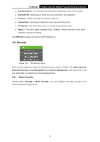
TL-MR3040 Portable 3G/3.75G Battery Powered Wireless N Router Figure 4-39 Port Triggering Once the Router is configured, the operation is as follows: 1. A local host makes an outgoing connection using a destination port number defined in the Trigger Port field. 2. The Router records this connection, opens the incoming port or ports associated with this entry in the Port Triggering table, and associates them with the local host. 3. When necessary the external host will be able to connect to the local host using one of the ports defined in the Incoming Ports field. ¾ Trigger Port - The port for outgoing traffic. An outgoing connection using this port will "Trigger" this rule. ¾ Trigger Protocol - The protocol used for Trigger Ports, either TCP, UDP, or All (all protocols supported by the Router). ¾ Incoming Port - The port or port range used by the remote system when it responds to the outgoing request. A response using one of these ports will be forwarded to the PC that triggered this rule. You can input at most 5 groups of ports (or port section). Every group of ports must be set apart with ",". For example, 2000-2038, 2050-2051, 2085, 3010-3030. ¾ Incoming Protocol - The protocol used for Incoming Ports Range, either TCP or UDP, or ALL (all protocols supported by the Router). ¾ Status - The status of this entry either Enabled or Disabled. To add a new rule, follow the steps below. 1. Click the Add New... button, the next screen will pop-up as shown in Figure 4-40. 2. Select a common application from the Common Applications drop-down list, then the Trigger Port field and the Incoming Ports field will be automatically filled. If the Common Applications do not have the application you need, enter the Trigger Port and the Incoming Ports manually. 3. Select the protocol used for Trigger Port from the Trigger Protocol drop-down list, either TCP, UDP, or All. 4. Select the protocol used for Incoming Ports from the Incoming Protocol drop-down list, either TCP or UDP, or All. 5. Select Enable in Status field. -60-
-
 1
1 -
2
-
3
-
4
-
5
-
6
-
7
-
8
-
9
-
10
-
11
-
12
-
13
-
14
-
15
-
16
-
17
-
18
-
19
-
20
-
21
-
22
-
23
-
24
-
25
-
26
-
27
-
28
-
29
-
30
-
31
-
32
-
33
-
34
-
35
-
36
-
37
-
38
-
39
-
40
-
41
-
42
-
43
-
44
-
45
-
46
-
47
-
48
-
49
-
50
-
51
-
52
-
53
-
54
-
55
-
56
-
57
-
58
-
59
-
60
-
61
-
62
-
63
-
64
-
 65
65 -
 66
66 -
 67
67 -
 68
68 -
 69
69 -
 70
70 -
 71
71 -
 72
72 -
 73
73 -
 74
74 -
 75
75 -
76
-
77
-
78
-
79
-
80
-
81
-
82
-
83
-
84
-
85
-
86
-
87
-
88
-
89
-
90
-
91
-
92
-
93
-
94
-
95
-
96
-
97
-
98
-
99
-
100
-
101
-
102
-
103
-
104
-
105
-
106
-
107
-
108
-
109
-
110
-
111
-
112
-
113
-
114
-
115
-
116
-
117
-
118
-
119
-
120
-
121
-
122
-
123
-
124
-
125
-
126
-
127
-
128
-
129
-
130
-
131
-
132
-
133
-
134
-
135
-
136
-
137
-
138
-
139
-
140
-
141
-
142
-
143
-
144
-
145
-
146
-
147
-
148
-
149
-
150
-
151
-
152
-
153
-
154
-
155
-
156
-
157
-
158
-
159
-
160
-
161
-
162
-
163
-
164
-
165
-
166
-
167
-
168
-
169
-
170
-
171
-
172
-
173
-
174
-
175
-
176
-
177
-
178
-
179
-
180
-
181
-
182
-
183
-
184
-
185
-
186
-
187
-
188
-
189
-
190
-
191
-
192
-
193
-
194
-
195
-
196
-
197
-
198
-
199
-
200
-
201
-
202
-
203
-
204
-
205
-
206
-
207
-
208
-
209
-
210
-
211
-
212
-
213
-
214
-
215
-
216
-
217
-
218
-
219
-
220
-
221
-
222
-
223
-
224
-
225
-
226
-
227
-
228
-
229
-
230
-
231
-
232
-
233
-
234
-
235
-
236
-
237
-
238
-
239
-
240
-
241
-
242
 |
 |
