3Com 3CRWE675075-UK User Guide - Page 18
Installing the, Locking Bar
 |
UPC - 662705477848
View all 3Com 3CRWE675075-UK manuals
Add to My Manuals
Save this manual to your list of manuals |
Page 18 highlights
12 CHAPTER 2: INSTALLING THE BRIDGE 2 Route the power and Ethernet cables through the large opening in the cradle. Figure 5 shows a cable being routed under the cradle. Figure 5 Routing Cable Under the Cradle 3 Connect the power and Ethernet cables to the ports on the Bridge. 4 Snap the Bridge onto the cradle. Installing the For additional security, install the locking bar in the cradle after the Bridge Locking Bar is mounted to the wall. Use your own lock to secure it in place. To install the locking bar: 1 Insert the locking bar through the opening in the side of the cradle, as shown in Figure 6. Figure 6 Inserting the Locking Bar .11a .11g .100 .10 Downloaded from www.Manualslib.com manuals search engine
-
 1
1 -
2
-
3
-
4
-
5
-
6
-
7
-
8
-
9
-
10
-
11
-
12
-
 13
13 -
 14
14 -
 15
15 -
 16
16 -
 17
17 -
 18
18 -
 19
19 -
 20
20 -
 21
21 -
 22
22 -
 23
23 -
24
-
25
-
26
-
27
-
28
-
29
-
30
-
31
-
32
-
33
-
34
-
35
-
36
-
37
-
38
-
39
-
40
-
41
-
42
-
43
-
44
-
45
-
46
-
47
-
48
-
49
-
50
-
51
-
52
-
53
-
54
-
55
-
56
-
57
-
58
-
59
-
60
-
61
-
62
-
63
-
64
-
65
-
66
-
67
-
68
-
69
-
70
 |
 |

12
C
HAPTER
2: I
NSTALLING
THE
B
RIDGE
2
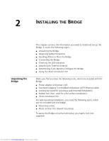
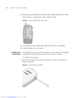
Route the power and Ethernet cables through the large opening in the cradle.
Figure 5 shows a cable being routed under the cradle.
Figure 5
Routing Cable Under the Cradle
3
Connect the power and Ethernet cables to the ports on the Bridge.
4
Snap the Bridge onto the cradle.
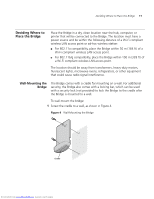
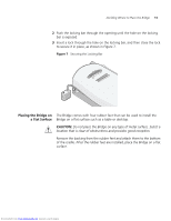
Installing the
Locking Bar
For additional security, install the locking bar in the cradle after the Bridge
is mounted to the wall. Use your own lock to secure it in place.
To install the locking bar:
1
Insert the locking bar through the opening in the side of the cradle, as
shown in Figure 6.
Figure 6
Inserting the Locking Bar
.11g
.100
.10
.11a
Downloaded from
www.Manualslib.com
manuals search engine