Brother International BAS-311E Network Users Manual - English - Page 113
With error code [E.E0], the [MN]
 |
View all Brother International BAS-311E manuals
Add to My Manuals
Save this manual to your list of manuals |
Page 113 highlights
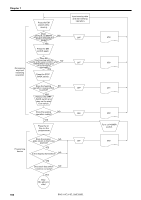
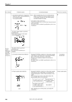
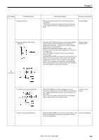
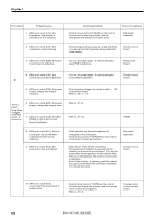
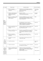
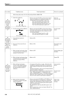
Chapter 7 Error status Probable cause 11. With error code [E.c4], overcurrent has occurred in Ypulse motor. 12. With error code [E.c5], the box cooling fan (at the right when viewed from the front) is defective. 13. With error code [E.E0], the [MN] PROM on the control circuit board is defective. #1 The power lamp does not light when the power is turned on. 14. With error code [E.F0], the relay on the power PCB is not working. Check/repair/adjust • Check that connector P6 (YPM) on the control circuit board is securely inserted and the Y-pulse motor is correctly wired. • Refer to #1.1-2 • Refer to #1.1-8 [E.CI] • Check that connector P25 (FAN-L) on the control circuit board is securely inserted. Parts to be replaced Y pulse motor control circuit board. Fan motor assembly • Check that the PROM of the control circuit board is securely inserted and its leads are not bend. • Check that MN and MT of the PROM are matching those on the main PCB. PRON • If the PROM has no problem, check the connection between pin 3 in connector P18 (PANEL) on the control circuit board and pin 5 in connector P5 (DRV) on the panel PCB. • Check that the PER code is securely inserted (refer to #1.1-15). If the error appears, replace the power PCB with a new one. Panel code Power PCB 15. With error code [E.F1], the cord is not securely inserted. 16. With error code [E.F2], overcurrent has occurred in power PCB. #1.2 No switches on the panel are not activated. 1. Panel PCB is not correctly attached. 2. Panel PCB is defective. 3. Programmer detective. #2 If the R/W switch is pressed, the indicator lamp is not lit and an error code appears. 1. With error code [E.40], the cord or the floppy disk drive (FDD) is defective. • Check that connector P2 (PER) of the power PCB and connector P20 (PER) on the main PCB are securely inserted. Check there is no damage in wiring. • Find a cause of noise. (Refer to #1.1-2.) • Replace the power PCB . (Refer to #1.1-14.) • Check whether the panel setting plate makes contact with a switch. • Refer to #1-7 • Pull out the programmer. If a switch is activated, the programmer is defective. • Check the connections and pins between connector P1 on the panel PCB and the FDD, and between connectors CH1 and CH2 on the panel PCB and the FDD. • Replace the floppy disk drive. PER code. Power PCB Panel circuit board Programmer FDD Harness Floppy disk drive BAS-311E.311EL.326E.326EL 105
-
 1
1 -
2
-
3
-
4
-
5
-
6
-
7
-
8
-
9
-
10
-
11
-
12
-
13
-
14
-
15
-
16
-
17
-
18
-
19
-
20
-
21
-
22
-
23
-
24
-
25
-
26
-
27
-
28
-
29
-
30
-
31
-
32
-
33
-
34
-
35
-
36
-
37
-
38
-
39
-
40
-
41
-
42
-
43
-
44
-
45
-
46
-
47
-
48
-
49
-
50
-
51
-
52
-
53
-
54
-
55
-
56
-
57
-
58
-
59
-
60
-
61
-
62
-
63
-
64
-
65
-
66
-
67
-
68
-
69
-
70
-
71
-
72
-
73
-
74
-
75
-
76
-
77
-
78
-
79
-
80
-
81
-
82
-
83
-
84
-
85
-
86
-
87
-
88
-
89
-
90
-
91
-
92
-
93
-
94
-
95
-
96
-
97
-
98
-
99
-
100
-
101
-
102
-
103
-
104
-
105
-
106
-
107
-
 108
108 -
 109
109 -
 110
110 -
 111
111 -
 112
112 -
 113
113 -
 114
114 -
 115
115 -
 116
116 -
 117
117 -
 118
118 -
119
-
120
-
121
-
122
-
123
-
124
-
125
-
126
-
127
-
128
-
129
-
130
-
131
-
132
-
133
-
134
-
135
-
136
-
137
-
138
-
139
-
140
-
141
-
142
-
143
-
144
-
145
-
146
-
147
-
148
-
149
-
150
 |
 |
