Brother International BAS-311E Network Users Manual - English - Page 117
Foot switch and cord defective, Panel circuit board is defective.
 |
View all Brother International BAS-311E manuals
Add to My Manuals
Save this manual to your list of manuals |
Page 117 highlights
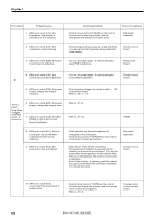
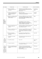
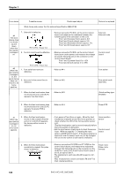
Chapter 7 Error status Probable causes #8 The work clamp does not move to the sewing start position. 1. Pulse motor has been out of control because of insufficient torque. (The feed mechanism does not move as programmed.) 2. Mechanical adjustment is not sufficient. 3. Pulse motor defective. 4. The control circuit board is defective. #9 The TEST lamp is not lit when the TEST switch is pressed. 1. Panel circuit board is defective. Check/repair/adjust Parts to be replaced • If the work clamp or material to be sewn is sluggish, set DIP switch B-8 to off and set the feed speed to low. • Turn the power off and then on again. Move the feed mechanism manually to check that it can easily move around the sewing area. • Refer to #7-4 • Refer to #1 and #2 (panel switch). Pulse motor Control circuit board. Panel circuit board #10 No feeding operation occurs during the test. • Refer to #6, #7, and #8 #11 Rapid feed can not be performed during the test. 1. Foot switch and cord defective • Refer to #4-1 #12 The machine does not operate as programm ed during the test. #13 The machine does not operate for sewing and error [E.20] appears. 1. Cord is defective. • Refer to #8 • Check that connector P3 (DC18) on the power PCB and connector P16 (DC18) on the control circuit board are securely inserted. • Check that connector P5 (DC300) on the power PCB and connector P15 (DC300) on the control circuit bard are securely inserted. • Check that connector P14 (UVW) on the control circuit board is securely inserted and there is no looseness of the machine motor. Power supply harness H-P Motor power cord. BAS-311E.311EL.326E.326EL 109
-
 1
1 -
2
-
3
-
4
-
5
-
6
-
7
-
8
-
9
-
10
-
11
-
12
-
13
-
14
-
15
-
16
-
17
-
18
-
19
-
20
-
21
-
22
-
23
-
24
-
25
-
26
-
27
-
28
-
29
-
30
-
31
-
32
-
33
-
34
-
35
-
36
-
37
-
38
-
39
-
40
-
41
-
42
-
43
-
44
-
45
-
46
-
47
-
48
-
49
-
50
-
51
-
52
-
53
-
54
-
55
-
56
-
57
-
58
-
59
-
60
-
61
-
62
-
63
-
64
-
65
-
66
-
67
-
68
-
69
-
70
-
71
-
72
-
73
-
74
-
75
-
76
-
77
-
78
-
79
-
80
-
81
-
82
-
83
-
84
-
85
-
86
-
87
-
88
-
89
-
90
-
91
-
92
-
93
-
94
-
95
-
96
-
97
-
98
-
99
-
100
-
101
-
102
-
103
-
104
-
105
-
106
-
107
-
108
-
109
-
110
-
111
-
 112
112 -
 113
113 -
 114
114 -
 115
115 -
 116
116 -
 117
117 -
 118
118 -
 119
119 -
 120
120 -
 121
121 -
 122
122 -
123
-
124
-
125
-
126
-
127
-
128
-
129
-
130
-
131
-
132
-
133
-
134
-
135
-
136
-
137
-
138
-
139
-
140
-
141
-
142
-
143
-
144
-
145
-
146
-
147
-
148
-
149
-
150
 |
 |
