Brother International BAS-311E Network Users Manual - English - Page 115
Power PCB defective., Pins 2 and 10 air valve for left work clamp
 |
View all Brother International BAS-311E manuals
Add to My Manuals
Save this manual to your list of manuals |
Page 115 highlights
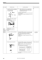
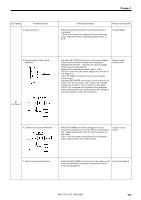
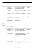
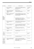
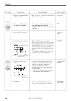
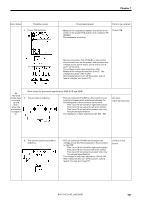
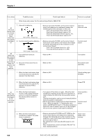
Chapter 7 Error status Probable causes 4. Power PCB defective. Check/repair/adjust Parts to be replaced • Measure the resistance between a terminal in the center of the power PCB and pin 2 in connector P5 (DC300). The resistance should be ∞Ω. Power PCB • Remove connector P12 (POWER) on the control circuit board, turn on the power, and measure the voltage across pins 4 and 6, pins 5 and 6, pins 5 and 7 on the cord. The voltage in each case should be +55V. Measure the voltage across pins 2 and 3. The voltage should be +20V to 24V. After measurement, turn off the power, wait at least 5 minutes, and insert P12. #4 The work clamp does not move up and down when the foot switch is stepped on. Work clamp for pneumatic specification (BAS-311E and 325E) 5. The air valve is defective. • Pull out connector P4 (AIR) on the control circuit board and measure the resistance between the following pins in the connector on the cord: Pins 1 and 10 (air valve for right work clamp) Pins 2 and 10 (air valve for left work clamp) Pins 3 and 10 (air valve for presser foot; only for optional specification) The resistance in each case should be 300 - 400 Ω. Air valve Valve harness assy. 6. The control circuit board (#3) is defective. • Pull out connector P4 (AIR) and measure the voltage across the following pins in the connector on the PCB: Pins 1 and 10 (air valve for right work clamp) Pins 2 and 10 (air valve for left work clamp) Pins 3 and 10 (air valve for presser foot; only for optional specification) The voltage in each case should be +20V to 24V. After measurement, turn off the power, wait at least 5 minutes, and insert P4. Control circuit board. BAS-311E.311EL.326E.326EL 107
-
 1
1 -
2
-
3
-
4
-
5
-
6
-
7
-
8
-
9
-
10
-
11
-
12
-
13
-
14
-
15
-
16
-
17
-
18
-
19
-
20
-
21
-
22
-
23
-
24
-
25
-
26
-
27
-
28
-
29
-
30
-
31
-
32
-
33
-
34
-
35
-
36
-
37
-
38
-
39
-
40
-
41
-
42
-
43
-
44
-
45
-
46
-
47
-
48
-
49
-
50
-
51
-
52
-
53
-
54
-
55
-
56
-
57
-
58
-
59
-
60
-
61
-
62
-
63
-
64
-
65
-
66
-
67
-
68
-
69
-
70
-
71
-
72
-
73
-
74
-
75
-
76
-
77
-
78
-
79
-
80
-
81
-
82
-
83
-
84
-
85
-
86
-
87
-
88
-
89
-
90
-
91
-
92
-
93
-
94
-
95
-
96
-
97
-
98
-
99
-
100
-
101
-
102
-
103
-
104
-
105
-
106
-
107
-
108
-
109
-
 110
110 -
 111
111 -
 112
112 -
 113
113 -
 114
114 -
 115
115 -
 116
116 -
 117
117 -
 118
118 -
 119
119 -
 120
120 -
121
-
122
-
123
-
124
-
125
-
126
-
127
-
128
-
129
-
130
-
131
-
132
-
133
-
134
-
135
-
136
-
137
-
138
-
139
-
140
-
141
-
142
-
143
-
144
-
145
-
146
-
147
-
148
-
149
-
150
 |
 |
