Brother International BAS-311E Network Users Manual - English - Page 116
between the following pins in the connector on the, control circuit board, and measure the resistance
 |
View all Brother International BAS-311E manuals
Add to My Manuals
Save this manual to your list of manuals |
Page 116 highlights
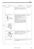
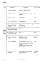
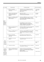
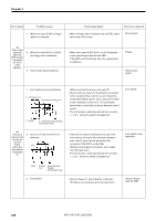
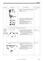
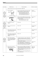
Chapter 7 Error status Probable causes Check/repair/adjust Parts to be replaced Work clamp and presser foot for solenoid specification (BAS-311E) #4 The work clamp does not move up and down when the foot switch is stepped on. 7. Solenoid is defective. Work clamp Presser foot 8. Control circuit board is defective. #6 When the start switch is stepped on, the work clamp does not return to its home position. Work clamp Presser foot 1. Foot switch and cord are defective. 2. Any cord in the control box is defective. • Remove connector P5 (SOL) on the control circuit board, and measure the resistance between the following pins in the connector on the cord: Pins 1 and 2 (presser foot): approx. 5-6 Ω. Pins 3 and 4 (work clamp): approx. 5-6 Ω. Pins 5 and 6 (thread trimmer): approx. 7-8 Ω. Pins 7 and 8 (thread wiper): approx. 6-7 Ω. • Remove connector P5 (SOL) on the control circuit board, turn on the power, and measure the voltage across the following pins in the connector on the control circuit board: Pins 1 and 2 (presser foot): 0 or +55V Pins 3 and 4 (work clamp): 0 or +55V • Refer to #4-1 • Refer to #4-2 Solenoid Solenoid code Control circuit board. Foot switch Foot switch code assembly 1. When the feed mechanism does not move and error code [E.A1] appears, fuse has blown. • Refer to #4-3 (Quick melting type 5A-250V) 2. When the feed mechanism does not move and error code [E.A1] appears, the power PCB is defective. • Refer to #4-4. Power PCB #7 When the start switch is stepped on, an error code appears. 3. When the feed mechanism moves in the unusual direction and error code [E.A1] appears, the home position sensor is defective. • Turn power off and then on again. Move the feed mechanism manually around the home position to check whether the LED of the home position sensor is lit. (The feed mechanism can be moved manually before the home position is detected.) • Set the input sensor check mode to check the sensor input. (Refer to page 90, "7. Checking the input sensor and DIP switch input".) If the above step (a) is approved, and the sensor input can not be changed, the cord or the control circuit board is defective. Home position sensor Control circuit board 4. When the feed mechanism operation is unusual, the pulse motor is defective. P6 (YPM) or P7 (XPM) • Remove connectors P6 (YPM) and P7 (XPM) on the control circuit board, and measure the resistance between the following pins in the connector on the cord:Pins 1 and 2, pins 2 and 3, pins 3 and 4, pins 4 and 5, and pins 5 and 1. The resistance in each case should be approx. 2.0 2.5 W. After measurement, return connectors P6 and P7 to their original positions. Pulse motor Pulse motor harness 108 BAS-311E.311EL.326E.326EL
-
 1
1 -
2
-
3
-
4
-
5
-
6
-
7
-
8
-
9
-
10
-
11
-
12
-
13
-
14
-
15
-
16
-
17
-
18
-
19
-
20
-
21
-
22
-
23
-
24
-
25
-
26
-
27
-
28
-
29
-
30
-
31
-
32
-
33
-
34
-
35
-
36
-
37
-
38
-
39
-
40
-
41
-
42
-
43
-
44
-
45
-
46
-
47
-
48
-
49
-
50
-
51
-
52
-
53
-
54
-
55
-
56
-
57
-
58
-
59
-
60
-
61
-
62
-
63
-
64
-
65
-
66
-
67
-
68
-
69
-
70
-
71
-
72
-
73
-
74
-
75
-
76
-
77
-
78
-
79
-
80
-
81
-
82
-
83
-
84
-
85
-
86
-
87
-
88
-
89
-
90
-
91
-
92
-
93
-
94
-
95
-
96
-
97
-
98
-
99
-
100
-
101
-
102
-
103
-
104
-
105
-
106
-
107
-
108
-
109
-
110
-
 111
111 -
 112
112 -
 113
113 -
 114
114 -
 115
115 -
 116
116 -
 117
117 -
 118
118 -
 119
119 -
 120
120 -
 121
121 -
122
-
123
-
124
-
125
-
126
-
127
-
128
-
129
-
130
-
131
-
132
-
133
-
134
-
135
-
136
-
137
-
138
-
139
-
140
-
141
-
142
-
143
-
144
-
145
-
146
-
147
-
148
-
149
-
150
 |
 |
