Brother International BAS-311E Network Users Manual - English - Page 118
power supply voltage has, When error code [E.90] appears
 |
View all Brother International BAS-311E manuals
Add to My Manuals
Save this manual to your list of manuals |
Page 118 highlights
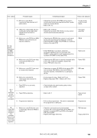
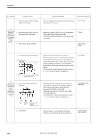
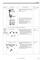
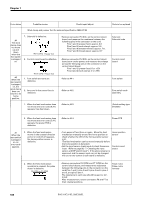
Chapter 7 Error status Probable causes #13 The machine does not operate for sewing and error [E.20] appears. 2. The control circuit board is defective. Red Black Check/repair/adjust Parts to be replaced • Remove connector P15 (DC300) on the control circuit board, and measure the resistance between pins 1 and 2 in the connector on the control circuit board. (A digital meter can not be used.) Using X1K Ω range, the needle should indicate 10K Ω -30K Ω. After measurement, return P15 to its original position. (If this measurement is not approved, check control circuit board fuses nos. 2, 3, and 4. They may be blown.) Control circuit board. 1. When error code [E.20] appears after the machine operates, the synchronizer is defective. #14 After the machine operates, an error code appears. 2. When error code [E.20] appears after the machine operates, the machine has been locked due to insufficient adjustment. 3. When error code [E.90] appears after the machine operates, the power supply voltage has sharply dropped. #15 The machine cannot sew patterns as programmed. 1. The synchronizer is defective. 2. The feed mechanism does not move as programmed. • Check that connector P2 (SYNCHRO) on the control circuit board is securely inserted and there is no damage in the synchronizer cable. Synchronizer assembly • Turn the pulley manually to check it can easily rotate. • Refer to #1.1-5 If the power supply capacity per machine is 600VA or more, the voltage sharply drops as soon as the machine starts, resulting this error to appear. • Refer to #14-1. Even if the synchronizer is defective, the test feeding will be performed correctly. Synchronizer assembly • Refer to #8-1, 2, 3, 4. 1. Mechanical adjustment is insufficient. • Remove the covers. If the solenoids for thread trimmer and thread wiper do not operate, check the following items. 2. The solenoid is defective. #16 Thread trimmer and thread wiper do not operate. Thread wiper Thread trimmer 3. The control circuit board is defective. Thread wiper Thread trimmer • Refer to #4-7. (When measuring for thread wiper, turn on the thread wiper switch.) Solenoid Solenoid harness • Remove connector P5 (SOL) on the control circuit board, turn on the power, start sewing, and measure the voltage across the following pins in the connector on the control circuit board: Pins 5 and 6 (thread trimming) Pins 7 and 8 (thread wiper) The voltage in each case should be output for an instance at the end of sewing. 110 BAS-311E.311EL.326E.326EL
-
 1
1 -
2
-
3
-
4
-
5
-
6
-
7
-
8
-
9
-
10
-
11
-
12
-
13
-
14
-
15
-
16
-
17
-
18
-
19
-
20
-
21
-
22
-
23
-
24
-
25
-
26
-
27
-
28
-
29
-
30
-
31
-
32
-
33
-
34
-
35
-
36
-
37
-
38
-
39
-
40
-
41
-
42
-
43
-
44
-
45
-
46
-
47
-
48
-
49
-
50
-
51
-
52
-
53
-
54
-
55
-
56
-
57
-
58
-
59
-
60
-
61
-
62
-
63
-
64
-
65
-
66
-
67
-
68
-
69
-
70
-
71
-
72
-
73
-
74
-
75
-
76
-
77
-
78
-
79
-
80
-
81
-
82
-
83
-
84
-
85
-
86
-
87
-
88
-
89
-
90
-
91
-
92
-
93
-
94
-
95
-
96
-
97
-
98
-
99
-
100
-
101
-
102
-
103
-
104
-
105
-
106
-
107
-
108
-
109
-
110
-
111
-
112
-
 113
113 -
 114
114 -
 115
115 -
 116
116 -
 117
117 -
 118
118 -
 119
119 -
 120
120 -
 121
121 -
 122
122 -
 123
123 -
124
-
125
-
126
-
127
-
128
-
129
-
130
-
131
-
132
-
133
-
134
-
135
-
136
-
137
-
138
-
139
-
140
-
141
-
142
-
143
-
144
-
145
-
146
-
147
-
148
-
149
-
150
 |
 |
