Compaq 100B Maintenance and Service Guide - Page 34
Installing DIMMs, CAUTION
 |
View all Compaq 100B manuals
Add to My Manuals
Save this manual to your list of manuals |
Page 34 highlights
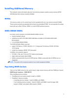
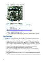
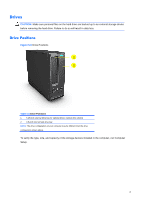
Figure 5-3 DIMM Socket Locations - 100B SFF PC Table 6-1 DIMM Socket Locations -100B SFF PC Item Description Socket Color 1 DIMM1 socket, Channel A Black (populate first) 2 DIMM2 socket, Channel A Blue NOTE: A DIMM must occupy the XMM1 socket. Insertion Order 1 2 The system only support single channel mode. ● In any mode, the maximum operational speed is determined by the slowest DIMM in the system. Installing DIMMs CAUTION: You must disconnect the power cord and wait approximately 30 seconds for the power to drain before adding or removing memory modules. Regardless of the power-on state, voltage is always supplied to the memory modules as long as the computer is plugged into an active AC outlet. Adding or removing memory modules while voltage is present may cause irreparable damage to the memory modules or system board. If you see an LED light on the system board, voltage is still present. The memory module sockets have gold-plated metal contacts. When upgrading the memory, it is important to use memory modules with gold-plated metal contacts to prevent corrosion and/or oxidation resulting from having incompatible metals in contact with each other. Static electricity can damage the electronic components of the computer or optional cards. Before beginning these procedures, ensure that you are discharged of static electricity by briefly touching a grounded metal object. When handling a memory module, be careful not to touch any of the contacts. Doing so may damage the module. 26
-
 1
1 -
2
-
3
-
4
-
5
-
6
-
7
-
8
-
9
-
10
-
11
-
12
-
13
-
14
-
15
-
16
-
17
-
18
-
19
-
20
-
21
-
22
-
23
-
24
-
25
-
26
-
27
-
28
-
 29
29 -
 30
30 -
 31
31 -
 32
32 -
 33
33 -
 34
34 -
 35
35 -
 36
36 -
 37
37 -
 38
38 -
 39
39 -
40
-
41
-
42
-
43
-
44
-
45
-
46
-
47
-
48
-
49
-
50
-
51
-
52
-
53
-
54
-
55
-
56
-
57
-
58
-
59
-
60
-
61
-
62
-
63
-
64
-
65
-
66
-
67
-
68
-
69
-
70
-
71
-
72
-
73
-
74
-
75
-
76
-
77
-
78
-
79
-
80
-
81
-
82
-
83
-
84
-
85
-
86
-
87
-
88
-
89
-
90
-
91
-
92
-
93
-
94
-
95
-
96
-
97
-
98
-
99
-
100
-
101
-
102
-
103
-
104
 |
 |
