Compaq 100B Maintenance and Service Guide - Page 36
Cable Management, Cable Connections, 100B SFF PC
 |
View all Compaq 100B manuals
Add to My Manuals
Save this manual to your list of manuals |
Page 36 highlights
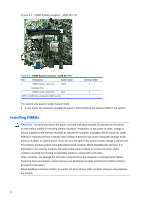
Cable Management The Small Form Factor chassis is a very compact computer and proper routing of the internal cables is critical to the operation of the computer. Follow good cable management practices when working inside the computer. ● Keep cables away from major heat sources like the heat sink. ● Do not jam cables on top of expansion cards or memory modules. Printed circuit cards like these are not designed to take excessive pressure on them. ● Keep cables clear of movable or rotating parts like the power supply and drive cage to prevent them from being cut or crimped when the component is lowered into its normal position. ● When folding a flat ribbon cable, never fold to a sharp crease. Sharp creases may damage the wires. ● Some flat ribbon cables come prefolded. Never change the folds on these cables. ● Do not bend any cable sharply. A sharp bend can break the internal wires. ● Never bend a SATA data cable tighter than a 30 mm (1.18 in) radius. ● Never crease a SATA data cable. ● Do not rely on components like the drive cage, power supply, or computer cover to push cables down into the chassis. Always position the cables to lay properly by themselves. When removing the power supply power cables from the connector on the system board, always follow these steps: 1. Squeeze on the top of the retaining latch attached to the cable end of the connector. 2. Grasp the cable end of the connector and pull it straight up. CAUTION: Always pull the connector - NEVER pull on the cable. Pulling on the cable could damage the cable and result in a failed power supply. Cable Connections 100B SFF PC System board connectors are color-coded to make it easier to find the proper connection. Connector Name Connector Color Description CPU_FAN white Heat sink fan F_USB2 black Media card reader JFP1 black Power switch F_AUDIO yellow Front I/O audio F_USB1 white Front I/O USB SATA1 dark blue Primary hard drive SATA2 white Primary optical drive 28
-
 1
1 -
2
-
3
-
4
-
5
-
6
-
7
-
8
-
9
-
10
-
11
-
12
-
13
-
14
-
15
-
16
-
17
-
18
-
19
-
20
-
21
-
22
-
23
-
24
-
25
-
26
-
27
-
28
-
29
-
30
-
 31
31 -
 32
32 -
 33
33 -
 34
34 -
 35
35 -
 36
36 -
 37
37 -
 38
38 -
 39
39 -
 40
40 -
 41
41 -
42
-
43
-
44
-
45
-
46
-
47
-
48
-
49
-
50
-
51
-
52
-
53
-
54
-
55
-
56
-
57
-
58
-
59
-
60
-
61
-
62
-
63
-
64
-
65
-
66
-
67
-
68
-
69
-
70
-
71
-
72
-
73
-
74
-
75
-
76
-
77
-
78
-
79
-
80
-
81
-
82
-
83
-
84
-
85
-
86
-
87
-
88
-
89
-
90
-
91
-
92
-
93
-
94
-
95
-
96
-
97
-
98
-
99
-
100
-
101
-
102
-
103
-
104
 |
 |
