D-Link DGS-1510-20 User Manual - Page 110
STP Bridge Global Settings, MSTI Config Information, MST Configuration, Identification
 |
View all D-Link DGS-1510-20 manuals
Add to My Manuals
Save this manual to your list of manuals |
Page 110 highlights
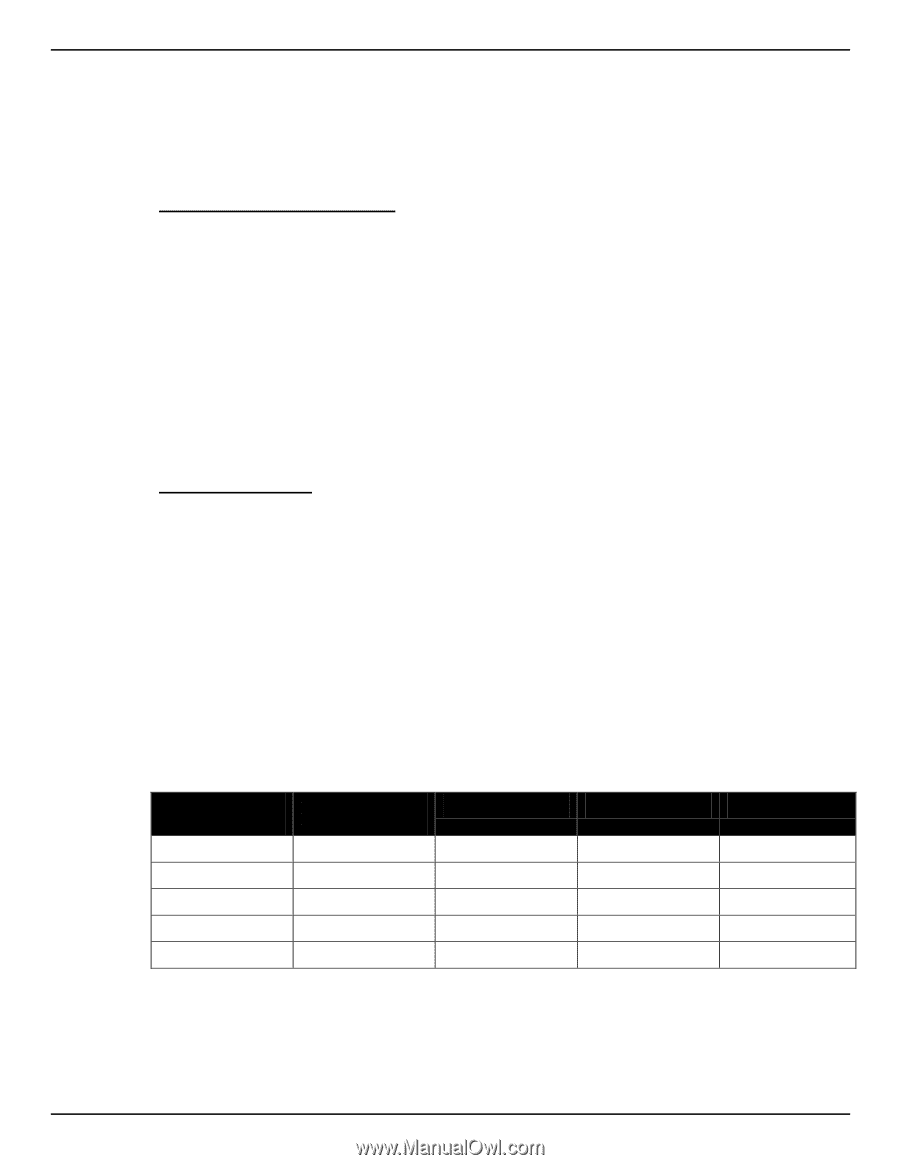
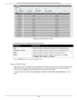
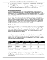
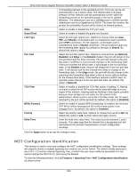
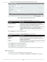
DGS-1510 Series Gigabit Ethernet SmartPro Switch Web UI Reference Guide 1. The Switch must be set to the MSTP setting (found in the STP Bridge Global Settings window in the STP Version field) 2. The correct spanning tree priority for the MSTP instance must be entered (defined here as a Priority in the MSTI Config Information window when configuring MSTI ID settings). 3. VLANs that will be shared must be added to the MSTP Instance ID (defined here as a VID List in the MST Configuration Identification window when configuring an MSTI ID settings). 802.1D-2004 Rapid Spanning Tree The Switch implements three versions of the Spanning Tree Protocol, the Multiple Spanning Tree Protocol (MSTP) as defined by the IEEE 802.1Q-2005, the Rapid Spanning Tree Protocol (RSTP) as defined by the IEEE 802.1D-2004 specification and a version compatible with the IEEE 802.1D-1998 STP. RSTP can operate with legacy equipment implementing IEEE 802.1D-1998; however the advantages of using RSTP will be lost. The IEEE 802.1D-2004 Rapid Spanning Tree Protocol (RSTP) evolved from the 802.1D-1998 STP standard. RSTP was developed in order to overcome some limitations of STP that impede the function of some recent switching innovations, in particular, certain Layer 3 functions that are increasingly handled by Ethernet switches. The basic function and much of the terminology is the same as STP. Most of the settings configured for STP are also used for RSTP. This section introduces some new Spanning Tree concepts and illustrates the main differences between the two protocols. Port Transition States An essential difference between the three protocols is in the way ports transition to a forwarding state and in the way this transition relates to the role of the port (forwarding or not forwarding) in the topology. MSTP and RSTP combine the transition states disabled, blocking and listening used in 802.1D-1998 and creates a single state Discarding. In either case, ports do not forward packets. In the STP port transition states disabled, blocking or listening or in the RSTP/MSTP port state discarding, there is no functional difference, the port is not active in the network topology. Table 7-3 below compares how the three protocols differ regarding the port state transition. All three protocols calculate a stable topology in the same way. Every segment will have a single path to the root bridge. All bridges listen for BPDU packets. However, BPDU packets are sent more frequently with every Hello packet. BPDU packets are sent even if a BPDU packet was not received. Therefore, each link between bridges is sensitive to the status of the link. Ultimately this difference results in faster detection of failed links, and thus faster topology adjustment. A drawback of 802.1D-1998 is this absence of immediate feedback from adjacent bridges. 802.1Q-2005 MSTP Disabled Discarding Discarding Learning Forwarding 802.1D-2004 RSTP Disabled Discarding Discarding Learning Forwarding 802.1D-1998 STP Forwarding Disabled No Blocking No Listening No Learning No Forwarding Yes Learning No No No Yes Yes RSTP is capable of a more rapid transition to a forwarding state - it no longer relies on timer configurations - RSTP compliant bridges are sensitive to feedback from other RSTP compliant bridge links. Ports do not need to wait for the topology to stabilize before transitioning to a forwarding state. In order to allow this rapid transition, the protocol introduces two new variables: the edge port and the pointto-point (P2P) port. 102
-
 1
1 -
2
-
3
-
4
-
5
-
6
-
7
-
8
-
9
-
10
-
11
-
12
-
13
-
14
-
15
-
16
-
17
-
18
-
19
-
20
-
21
-
22
-
23
-
24
-
25
-
26
-
27
-
28
-
29
-
30
-
31
-
32
-
33
-
34
-
35
-
36
-
37
-
38
-
39
-
40
-
41
-
42
-
43
-
44
-
45
-
46
-
47
-
48
-
49
-
50
-
51
-
52
-
53
-
54
-
55
-
56
-
57
-
58
-
59
-
60
-
61
-
62
-
63
-
64
-
65
-
66
-
67
-
68
-
69
-
70
-
71
-
72
-
73
-
74
-
75
-
76
-
77
-
78
-
79
-
80
-
81
-
82
-
83
-
84
-
85
-
86
-
87
-
88
-
89
-
90
-
91
-
92
-
93
-
94
-
95
-
96
-
97
-
98
-
99
-
100
-
101
-
102
-
103
-
104
-
 105
105 -
 106
106 -
 107
107 -
 108
108 -
 109
109 -
 110
110 -
 111
111 -
 112
112 -
 113
113 -
 114
114 -
 115
115 -
116
-
117
-
118
-
119
-
120
-
121
-
122
-
123
-
124
-
125
-
126
-
127
-
128
-
129
-
130
-
131
-
132
-
133
-
134
-
135
-
136
-
137
-
138
-
139
-
140
-
141
-
142
-
143
-
144
-
145
-
146
-
147
-
148
-
149
-
150
-
151
-
152
-
153
-
154
-
155
-
156
-
157
-
158
-
159
-
160
-
161
-
162
-
163
-
164
-
165
-
166
-
167
-
168
-
169
-
170
-
171
-
172
-
173
-
174
-
175
-
176
-
177
-
178
-
179
-
180
-
181
-
182
-
183
-
184
-
185
-
186
-
187
-
188
-
189
-
190
-
191
-
192
-
193
-
194
-
195
-
196
-
197
-
198
-
199
-
200
-
201
-
202
-
203
-
204
-
205
-
206
-
207
-
208
-
209
-
210
-
211
-
212
-
213
-
214
-
215
-
216
-
217
-
218
-
219
-
220
-
221
-
222
-
223
-
224
-
225
-
226
-
227
-
228
-
229
-
230
-
231
-
232
-
233
-
234
-
235
-
236
-
237
-
238
-
239
-
240
-
241
-
242
-
243
-
244
-
245
-
246
-
247
-
248
-
249
-
250
-
251
-
252
-
253
-
254
-
255
-
256
-
257
-
258
-
259
-
260
-
261
-
262
-
263
-
264
-
265
-
266
-
267
-
268
-
269
-
270
-
271
-
272
-
273
-
274
-
275
-
276
-
277
-
278
-
279
-
280
-
281
-
282
-
283
-
284
-
285
-
286
-
287
-
288
-
289
-
290
-
291
-
292
-
293
-
294
-
295
-
296
-
297
-
298
-
299
-
300
-
301
-
302
-
303
-
304
-
305
-
306
-
307
-
308
-
309
-
310
-
311
-
312
-
313
-
314
-
315
-
316
-
317
-
318
-
319
-
320
-
321
-
322
-
323
-
324
-
325
-
326
-
327
-
328
-
329
-
330
-
331
-
332
-
333
-
334
-
335
-
336
-
337
-
338
-
339
-
340
-
341
-
342
-
343
-
344
-
345
-
346
-
347
-
348
-
349
-
350
-
351
-
352
-
353
-
354
-
355
-
356
-
357
-
358
-
359
-
360
-
361
-
362
-
363
-
364
-
365
-
366
-
367
-
368
-
369
-
370
-
371
-
372
-
373
-
374
-
375
-
376
-
377
-
378
-
379
-
380
-
381
-
382
-
383
-
384
-
385
-
386
-
387
-
388
-
389
-
390
-
391
-
392
-
393
-
394
-
395
-
396
-
397
-
398
-
399
-
400
-
401
-
402
-
403
-
404
-
405
-
406
-
407
-
408
-
409
-
410
-
411
-
412
-
413
-
414
-
415
-
416
-
417
-
418
-
419
-
420
-
421
-
422
-
423
-
424
-
425
-
426
-
427
-
428
-
429
-
430
 |
 |