D-Link DGS-1510-20 User Manual - Page 232
Start Sequence No., Counter State
 |
View all D-Link DGS-1510-20 manuals
Add to My Manuals
Save this manual to your list of manuals |
Page 232 highlights
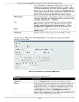
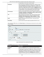
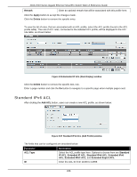
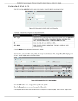
DGS-1510 Series Gigabit Ethernet SmartPro Switch Web UI Reference Guide Destination IP Precedence ToS DSCP Time Range traffic will be evaluated according to the conditions of this rule. When the Host option is selected, enter the source host's IP address here. When the IP option is selected, the Wildcard option will also be available. Enter the group of source IP addresses by using a wildcard bitmap. The bit corresponding to the bit value 1 will be ignored. The bit corresponding to the bit value 0 will be checked. Select and enter the destination information here. Options to choose from are Any, Host, and IP. When the Any option is selected, any destination traffic will be evaluated according to the conditions of this rule. When the Host option is selected, enter the destination host's IP address here. When the IP option is selected, the Wildcard option will also be available. Enter the group of destination IP addresses by using a wildcard bitmap. The bit corresponding to the bit value 1 will be ignored. The bit corresponding to the bit value 0 will be checked. Select the IP precedence value used here. Options to choose from are 0 (routine), 1 (priority), 2, (immediate), 3 (flash), 4 (flash-override), 5 (critical), 6 (internet), and 7 (network). After selecting the IP precedence value, select the Type-of-Service (ToS) value that will be used here. Options to choose from are 0 (normal), 1 (min-monetary-cost), 2 (max-reliability), 3, 4 (maxthroughput), 5, 6, 7, 8 (min-delay), 9, 10, 11, 12, 13, 14, and 15. Select or enter the DSCP value used here. This value must be between 0 and 63. Enter the name of the time range to associate with this ACL rule. Click the Back button to discard the changes made and return to the previous page. Click the Apply button to accept the changes made. To enable the Counter State option or to enter a Remark for the profile, click the Edit button, next to the specific ACL profile (found in the ACL profile table). Figure 8-55 Extended IP ACL (Edit ACL) window The fields that can be configured are described below: Parameter Start Sequence No. Step Counter State Description Enter the start sequence number here. Enter the sequence number increment here. Select to enable or disable the counter state option here. 224
-
 1
1 -
2
-
3
-
4
-
5
-
6
-
7
-
8
-
9
-
10
-
11
-
12
-
13
-
14
-
15
-
16
-
17
-
18
-
19
-
20
-
21
-
22
-
23
-
24
-
25
-
26
-
27
-
28
-
29
-
30
-
31
-
32
-
33
-
34
-
35
-
36
-
37
-
38
-
39
-
40
-
41
-
42
-
43
-
44
-
45
-
46
-
47
-
48
-
49
-
50
-
51
-
52
-
53
-
54
-
55
-
56
-
57
-
58
-
59
-
60
-
61
-
62
-
63
-
64
-
65
-
66
-
67
-
68
-
69
-
70
-
71
-
72
-
73
-
74
-
75
-
76
-
77
-
78
-
79
-
80
-
81
-
82
-
83
-
84
-
85
-
86
-
87
-
88
-
89
-
90
-
91
-
92
-
93
-
94
-
95
-
96
-
97
-
98
-
99
-
100
-
101
-
102
-
103
-
104
-
105
-
106
-
107
-
108
-
109
-
110
-
111
-
112
-
113
-
114
-
115
-
116
-
117
-
118
-
119
-
120
-
121
-
122
-
123
-
124
-
125
-
126
-
127
-
128
-
129
-
130
-
131
-
132
-
133
-
134
-
135
-
136
-
137
-
138
-
139
-
140
-
141
-
142
-
143
-
144
-
145
-
146
-
147
-
148
-
149
-
150
-
151
-
152
-
153
-
154
-
155
-
156
-
157
-
158
-
159
-
160
-
161
-
162
-
163
-
164
-
165
-
166
-
167
-
168
-
169
-
170
-
171
-
172
-
173
-
174
-
175
-
176
-
177
-
178
-
179
-
180
-
181
-
182
-
183
-
184
-
185
-
186
-
187
-
188
-
189
-
190
-
191
-
192
-
193
-
194
-
195
-
196
-
197
-
198
-
199
-
200
-
201
-
202
-
203
-
204
-
205
-
206
-
207
-
208
-
209
-
210
-
211
-
212
-
213
-
214
-
215
-
216
-
217
-
218
-
219
-
220
-
221
-
222
-
223
-
224
-
225
-
226
-
 227
227 -
 228
228 -
 229
229 -
 230
230 -
 231
231 -
 232
232 -
 233
233 -
 234
234 -
 235
235 -
 236
236 -
 237
237 -
238
-
239
-
240
-
241
-
242
-
243
-
244
-
245
-
246
-
247
-
248
-
249
-
250
-
251
-
252
-
253
-
254
-
255
-
256
-
257
-
258
-
259
-
260
-
261
-
262
-
263
-
264
-
265
-
266
-
267
-
268
-
269
-
270
-
271
-
272
-
273
-
274
-
275
-
276
-
277
-
278
-
279
-
280
-
281
-
282
-
283
-
284
-
285
-
286
-
287
-
288
-
289
-
290
-
291
-
292
-
293
-
294
-
295
-
296
-
297
-
298
-
299
-
300
-
301
-
302
-
303
-
304
-
305
-
306
-
307
-
308
-
309
-
310
-
311
-
312
-
313
-
314
-
315
-
316
-
317
-
318
-
319
-
320
-
321
-
322
-
323
-
324
-
325
-
326
-
327
-
328
-
329
-
330
-
331
-
332
-
333
-
334
-
335
-
336
-
337
-
338
-
339
-
340
-
341
-
342
-
343
-
344
-
345
-
346
-
347
-
348
-
349
-
350
-
351
-
352
-
353
-
354
-
355
-
356
-
357
-
358
-
359
-
360
-
361
-
362
-
363
-
364
-
365
-
366
-
367
-
368
-
369
-
370
-
371
-
372
-
373
-
374
-
375
-
376
-
377
-
378
-
379
-
380
-
381
-
382
-
383
-
384
-
385
-
386
-
387
-
388
-
389
-
390
-
391
-
392
-
393
-
394
-
395
-
396
-
397
-
398
-
399
-
400
-
401
-
402
-
403
-
404
-
405
-
406
-
407
-
408
-
409
-
410
-
411
-
412
-
413
-
414
-
415
-
416
-
417
-
418
-
419
-
420
-
421
-
422
-
423
-
424
-
425
-
426
-
427
-
428
-
429
-
430
 |
 |