D-Link DMS-1100 User Manual - Page 10
DMS-1100-10TP, Front Panel, Rear Panel
 |
View all D-Link DMS-1100 manuals
Add to My Manuals
Save this manual to your list of manuals |
Page 10 highlights
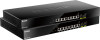
D-Link DMS-1100 Series User Manual DMS-1100-10TP 8-port 2.5GBASE-T PoE+ and 2-port 10G SFP+ Smart Managed Switch. Front Panel Figure 1.3 - DMS-1100-10TP Front Panel Power LED : The Power LED lights up when the Switch is connected to a power source. Fan Error: The Fan error LED lights up when the fan has runtime failure and is brought offline. Reset: Press the Reset button for 1~5 seconds to reboot the device. Press the Reset button for 6~10 seconds to reset the Switch back to the default settings and led will be solid light with amber for 2 seconds. Or press the Reset button over 11 seconds to enter the loader mode after device reboot and the led will be solid light with green for 2 seconds. If the device cannot reboot the Switch, the device will enter the loader mode automatically. PoE OK/FAIL: The PoE LED shows the status of the PoE ports, the green light (OK) indicates that PoE work fine and the amber light (Fail) indicate that the PoE is working abnormally. Port Link/Act/Speed LED (1-8): The port LEDs indicate a network link through the corresponding port. Blinking indicates the Switch is either sending or receiving data to the port. When the port LED glows amber, it indicates the port is running at 100 Mbps or 1000 Mbps. When the port LED glows green, it is running at 2.5 Gbps. Port Link/Act/Speed LED (9F, 10F): The port LEDs indicate a network link through the corresponding port. Blinking indicates the Switch is either sending or receiving data to the port. When the port LED glows green, it is running at 1000 Mbps or 10 Gbps. CAUTION: The MiniGBIC ports should use UL listed Optical Transceiver product, Rated Laser Class I. 3.3Vdc. Rear Panel PRUDENCE: Si le transceiveur optique n'est pas livré avec l'appareil, le manuel d'utilisation doit comporter la description ci-dessous ou son équivalent :« Ce produit est destiné à être utilisé avec un transceiveur optique homologué UL,tension DC3.3V, classe laser I. Figure 1.4 - DMS-1110-10TP Rear Panel Power: Connect the AC power cord to this port. 4
-
 1
1 -
2
-
3
-
4
-
 5
5 -
 6
6 -
 7
7 -
 8
8 -
 9
9 -
 10
10 -
 11
11 -
 12
12 -
 13
13 -
 14
14 -
 15
15 -
16
-
17
-
18
-
19
-
20
-
21
-
22
-
23
-
24
-
25
-
26
-
27
-
28
-
29
-
30
-
31
-
32
-
33
-
34
-
35
-
36
-
37
-
38
-
39
-
40
-
41
-
42
-
43
-
44
-
45
-
46
-
47
-
48
-
49
-
50
-
51
-
52
-
53
-
54
-
55
-
56
-
57
-
58
-
59
-
60
-
61
-
62
-
63
-
64
-
65
-
66
-
67
-
68
-
69
-
70
-
71
-
72
-
73
-
74
-
75
-
76
-
77
-
78
-
79
-
80
-
81
-
82
-
83
-
84
-
85
-
86
-
87
-
88
-
89
-
90
-
91
-
92
-
93
-
94
-
95
-
96
-
97
-
98
-
99
-
100
-
101
-
102
-
103
-
104
-
105
-
106
-
107
-
108
-
109
-
110
-
111
-
112
-
113
-
114
-
115
-
116
-
117
-
118
 |
 |
