Dell PowerEdge MX7000 EMC OpenManage Enterprise-Modular Edition Version 1.20.1 - Page 82
Recommended physical topology
 |
View all Dell PowerEdge MX7000 manuals
Add to My Manuals
Save this manual to your list of manuals |
Page 82 highlights
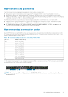
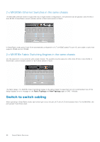
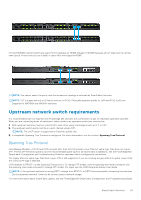
Recommended physical topology The recommended minimum design for a scalable fabric is two chassis with Fabric A populated with redundant IOMs. Ideally, the two chassis are located in separate racks on separate power circuits to provide the highest redundancy. Additional chassis only have FEMs and the appear as the image below. Table 13. Fabric topology Chassis Slot Chassis 1 A1 A2 Chassis 2 A1 A2 Chassis 3-10 A1 A2 You can also use Fabric B to create a second scalable fabric: Module MX9116n FSE MX7116n FEM MX7116n FEM MX9116n FSE MX7116n FEM MX7116n FEM NOTE: The OME-Modular firmware version 1.20.10 supports additional but complex topologies and also Quad Port Ethernet adapters. For more information, see the PowerEdge MX Network Architecture Guide available at https:// infohub.delltechnologies.com/t/mx-series-modular-switches-poweredge-mx-7/. 82 MX Scalable Fabric architecture
-
 1
1 -
2
-
3
-
4
-
5
-
6
-
7
-
8
-
9
-
10
-
11
-
12
-
13
-
14
-
15
-
16
-
17
-
18
-
19
-
20
-
21
-
22
-
23
-
24
-
25
-
26
-
27
-
28
-
29
-
30
-
31
-
32
-
33
-
34
-
35
-
36
-
37
-
38
-
39
-
40
-
41
-
42
-
43
-
44
-
45
-
46
-
47
-
48
-
49
-
50
-
51
-
52
-
53
-
54
-
55
-
56
-
57
-
58
-
59
-
60
-
61
-
62
-
63
-
64
-
65
-
66
-
67
-
68
-
69
-
70
-
71
-
72
-
73
-
74
-
75
-
76
-
 77
77 -
 78
78 -
 79
79 -
 80
80 -
 81
81 -
 82
82 -
 83
83 -
 84
84 -
 85
85 -
 86
86 -
 87
87 -
88
-
89
-
90
-
91
-
92
-
93
-
94
-
95
-
96
-
97
-
98
-
99
-
100
-
101
-
102
-
103
-
104
-
105
-
106
-
107
-
108
-
109
-
110
-
111
-
112
-
113
-
114
-
115
-
116
-
117
-
118
-
119
-
120
-
121
-
122
-
123
-
124
-
125
-
126
-
127
 |
 |
