Dell PowerEdge MX7000 EMC OpenManage Enterprise-Modular Edition Version 1.20.1 - Page 89
Adding uplinks, Include in Uplink Failure Detection Group
 |
View all Dell PowerEdge MX7000 manuals
Add to My Manuals
Save this manual to your list of manuals |
Page 89 highlights
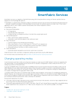
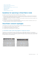
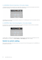
● 2xMX9116n Fabric Switching Engines in different chassis Based on the design type selected, the options to select the chassis and the switches-A and B, are displayed. 5. Select the chassis and switches. The cabling image is displayed. 6. Click Next to view the summary of the fabric. You can print to print a hard copy of the fabric details or save the details as a PDF on your system. After the fabric is created, the switch is placed in the SmartFabric mode and the IOM reboots. NOTE: After a fabric is created, the health status of the fabric is critical until uplinks are created. NOTE: The fabric health alerts are displayed on all chassis in the MCM group. Adding uplinks To add uplinks: 1. From the Devices drop-down, select Fabric. The Fabric page is displayed. 2. From the fabrics table, select the fabric and click View Details. The Fabric Details page is displayed. 3. From the Uplinks section, click Add Uplink. The Add Uplink window is displayed. 4. Enter Name, Description, select the Uplink Type. The available options are: ● Ethernet - No Spanning Tree- You must pick at least one Ethernet port from each switch to form a LAG. Any Ethernet traffic can be passed on this uplink type. This uplink type does not require Spanning Tree Protocol to be configured on the upstream Ethernet switch. For more information about how to configure the upstream Ethernet switch, see Dell EMC PowerEdge MX SmartFabric Configuration and Troubleshooting Guide at https:// infohub.delltechnologies.com/. Before you can create an Ethernet - No STP uplink, all legacy Ethernet uplinks that use STP must be deleted. There are additional steps that must be completed before creating an Ethernet - No STP uplink on an existing fabric that was not running the RSTP protocol. For more information, see the Dell EMC PowerEdge MX SmartFabric Configuration and Troubleshooting Guide at https://infohub.delltechnologies.com/ ● FCoE-You can pick one port from an IOM and associate a single network of FCoE type. This is for FCoE connectivity that connects to another switch that connects to the FC network. For single fabric, you can have two FCoE uplink, one from each IOM. Both IOMs must have different network that is, different FCoE VLANs. In FCoE mode, untagged VLAN on the server port and FCoE uplink must be the same. This condition ensures that the untagged FIP VLAN discovery (L2 frame) packets are switched to the untagged VLAN. The FCoE uplink is used to identify FIP Snooping Bridge (FSB) mode at the switch. For the FCoE sessions to come up, configure the same untagged VLAN on FCoE uplinks and server ports. NOTE: On the uplink FCoE switch, use the default fc-map (0efc00) only. ● FC Gateway-You can pick one or more ports from the same IOM and associate a single network of FCoE type. This type of uplink is for connectivity to a SAN switch. For single Fabric, you can have two FC gateway uplinks one from each IOM. Both IOMs must have different network that is, different FCoE VLANs. For a given fabric, you can have at least one uplink of type FC (either of FCoE, FCDirectAttach, FC Gateway). In Fabric mode, you can assign any untagged VLAN to Ethernet server ports that belong to a FCoE VLAN that has one or more FC Gateway uplinks. The FC Gateway uplink is used to identify NPG (N Port Proxy Gateway) mode at the switch. ● FC Direct Attach-You can pick one or more ports from same IOM and associate a single network of FCoE type. This type of uplink is for direct FC storage connectivity. For single fabric, user can have two FC DirectAttach uplink, one from each IOM. Both IOMs must have different networks that is, different FCoE VLANs. In Fabric mode, you can assign any untagged VLAN to Ethernet server ports that belong to a FCoE VLAN that has one or more FC Direct attach uplinks. The FC Direct attach uplink is used to identify F-Port mode at the switch. ● Ethernet-You can pick one or more Ethernet ports across switches to form a LAG. The network can be of any type. Also, you must configure Spanning Tree on the upstream network switch. 5. Select Include in Uplink Failure Detection Group. and click Next. SmartFabric Services 89
-
 1
1 -
2
-
3
-
4
-
5
-
6
-
7
-
8
-
9
-
10
-
11
-
12
-
13
-
14
-
15
-
16
-
17
-
18
-
19
-
20
-
21
-
22
-
23
-
24
-
25
-
26
-
27
-
28
-
29
-
30
-
31
-
32
-
33
-
34
-
35
-
36
-
37
-
38
-
39
-
40
-
41
-
42
-
43
-
44
-
45
-
46
-
47
-
48
-
49
-
50
-
51
-
52
-
53
-
54
-
55
-
56
-
57
-
58
-
59
-
60
-
61
-
62
-
63
-
64
-
65
-
66
-
67
-
68
-
69
-
70
-
71
-
72
-
73
-
74
-
75
-
76
-
77
-
78
-
79
-
80
-
81
-
82
-
83
-
 84
84 -
 85
85 -
 86
86 -
 87
87 -
 88
88 -
 89
89 -
 90
90 -
 91
91 -
 92
92 -
 93
93 -
 94
94 -
95
-
96
-
97
-
98
-
99
-
100
-
101
-
102
-
103
-
104
-
105
-
106
-
107
-
108
-
109
-
110
-
111
-
112
-
113
-
114
-
115
-
116
-
117
-
118
-
119
-
120
-
121
-
122
-
123
-
124
-
125
-
126
-
127
 |
 |
