Dell XPS M1210 MXC062 XPS M1210 Service Manual - Page 42
System Board: Dell XPS M1210 Service Manual, Removing the System Board
 |
View all Dell XPS M1210 MXC062 manuals
Add to My Manuals
Save this manual to your list of manuals |
Page 42 highlights
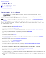
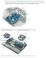
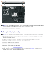
Back to Contents Page System Board Dell™ XPS™ M1210 Service Manual Removing the System Board Replacing the System Board Removing the System Board CAUTION: Before you begin the following procedure, follow the safety instructions in the Product Information Guide. NOTICE: To avoid electrostatic discharge, ground yourself by using a wrist grounding strap or by periodically touching an unpainted metal surface (such as the back panel) on the computer. NOTICE: To help prevent damage to the system board, remove the main battery (see Before Working Inside Your Computer) before working inside the computer. The system board's BIOS chip contains the Service Tag, which is also visible on a barcode label on the bottom of the computer. The replacement kit for the system board includes a CD that provides a utility for transferring the Service Tag to the replacement system board. 1. Follow the instructions in Before Working Inside Your Computer. 2. Remove the hard drive (see Removing the Hard Drive). 3. Remove the optical drive (see Optical Drive). 4. Remove the memory module accessible from the bottom of the computer (see Removing the Memory Module(s)). 5. Remove any installed WLAN and/or Mobile Broadband Mini-Cards (see Mini-Cards). 6. Remove the hinge cover (see Removing the Hinge Cover). 7. Remove the keyboard (see Keyboard). 8. Remove the memory module accessible from the top of the computer, underneath the keyboard (see Removing the Memory Module(s)). 9. Remove the display assembly (see Removing the Display Assembly). 10. Remove the palm rest (see Removing the Palm Rest). 11. Remove the modem (see Removing the Modem). 12. Remove the hard drive bay/ExpressCard cage assembly (see Hard Drive Bay/ExpressCard Cage Assembly. 13. Disconnect the modem cable connector from the system board. 14. Disconnect the connector for the internal card with Bluetooth® wireless technology from the system board. 15. Remove the thermal-cooling assembly (see Removing the Thermal-Cooling Assembly). 16. Remove the processor (see Removing the Processor Module). 17. Remove the two M2.5 x 5-mm screws that secure the input/output daughter card to the system board, and remove the card from the computer base. 18. Remove the system board, slowly easing the connectors out of their access holes on the back and side of the computer base:
-
 1
1 -
2
-
3
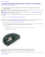
-
4
-
5
-
6
-
7
-
8
-
9
-
10
-
11
-
12
-
13
-
14
-
15
-
16
-
17
-
18
-
19
-
20
-
21
-
22
-
23
-
24
-
25
-
26
-
27
-
28
-
29
-
30
-
31
-
32
-
33
-
34
-
35
-
36
-
 37
37 -
 38
38 -
 39
39 -
 40
40 -
 41
41 -
 42
42 -
 43
43 -
 44
44 -
 45
45 -
 46
46 -
 47
47 -
48
-
49
-
50
-
51
-
52
-
53
-
54
-
55
-
56
-
57
 |
 |
