Dell XPS M1210 MXC062 XPS M1210 Service Manual - Page 49
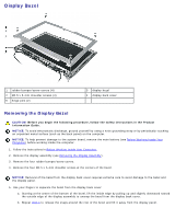
Display Panel, Replacing the Display Bezel
 |
View all Dell XPS M1210 MXC062 manuals
Add to My Manuals
Save this manual to your list of manuals |
Page 49 highlights
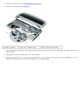
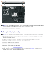
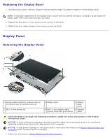
Replacing the Display Bezel 1. Starting at any corner, use your fingers to gently snap the bezel into place to secure it to the display panel. NOTE: To facilitate replacement of the display bezel, ensure that the camera connector is tucked in place beside the display panel before you snap the bezel into place. 2. Replace the four M2.5 x 5-mm screws on the corners of the bezel. 3. Replace the four rubber bumper/screw covers around the bezel. Display Panel Removing the Display Panel 1 camera cable connector (present only on computers with an optional camera) 2 M2 x 3-mm screws (4) 3 display panel 5 display back cover 4 M2 x 3-mm display-cable 6 speaker ground screw and ground wire cable CAUTION: Before you begin the following procedure, follow the safety instructions in the Product Information Guide. NOTICE: To avoid electrostatic discharge, ground yourself by using a wrist grounding strap or by touching an unpainted metal surface (such as the back panel) on the computer. NOTICE: To help prevent damage to the system board, remove the main battery (see Before Working Inside Your Computer) before working inside the computer. 1. Follow the instructions in Before Working Inside Your Computer.
-
 1
1 -
2
-
3
-
4
-
5
-
6
-
7
-
8
-
9
-
10
-
11
-
12
-
13
-
14
-
15
-
16
-
17
-
18
-
19
-
20
-
21
-
22
-
23
-
24
-
25
-
26
-
27
-
28
-
29
-
30
-
31
-
32
-
33
-
34
-
35
-
36
-
37
-
38
-
39
-
40
-
41
-
42
-
43
-
 44
44 -
 45
45 -
 46
46 -
 47
47 -
 48
48 -
 49
49 -
 50
50 -
 51
51 -
 52
52 -
 53
53 -
 54
54 -
55
-
56
-
57
 |
 |
