Dell XPS M1210 MXC062 XPS M1210 Service Manual - Page 47
Replacing the Display Assembly, If no Mini- Cards are
 |
View all Dell XPS M1210 MXC062 manuals
Add to My Manuals
Save this manual to your list of manuals |
Page 47 highlights
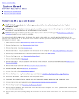
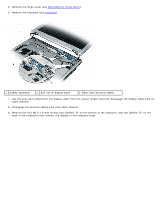
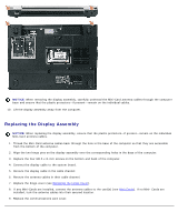
NOTICE: When removing the display assembly, carefully unthread the Mini-Card antenna cables through the computer base and ensure that the plastic protectors-if present-remain on the individual cables. 10. Lift the display assembly away from the computer. Replacing the Display Assembly NOTICE: When replacing the display assembly, ensure that the plastic protectors-if present-remain on the individual Mini-Card antenna cables. 1. Thread the Mini-Card antenna cables back through the hole in the base of the computer so that they are accessible from the bottom of the computer. 2. Align the two hinge pins on the display assembly over the corresponding holes in the base of the computer. 3. Replace the four M2.5 x 8-mm screws on the bottom and back of the computer. 4. Connect the display cable to the system board. 5. Reroute the display cable in the cable channel. 6. Reroute the antenna cables in their cable channel. 7. Replace the hinge cover (see Replacing the Hinge Cover). 8. If any Mini-Cards are installed, connect the antenna cables to the card(s) (see Mini-Cards). If no Mini- Cards are installed, tuck the antenna cables into their secured location. 9. Replace the communications card cover.
-
 1
1 -
2
-
3
-
4
-
5
-
6
-
7
-
8
-
9
-
10
-
11
-
12
-
13
-
14
-
15
-
16
-
17
-
18
-
19
-
20
-
21
-
22
-
23
-
24
-
25
-
26
-
27
-
28
-
29
-
30
-
31
-
32
-
33
-
34
-
35
-
36
-
37
-
38
-
39
-
40
-
41
-
 42
42 -
 43
43 -
 44
44 -
 45
45 -
 46
46 -
 47
47 -
 48
48 -
 49
49 -
 50
50 -
 51
51 -
 52
52 -
53
-
54
-
55
-
56
-
57
 |
 |
