Dell XPS M1210 MXC062 XPS M1210 Service Manual - Page 50
Replacing the Display Panel
 |
View all Dell XPS M1210 MXC062 manuals
Add to My Manuals
Save this manual to your list of manuals |
Page 50 highlights
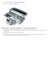
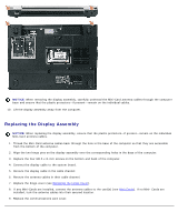
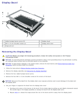
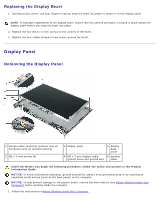
2. Remove the display assembly (see Removing the Display Assembly). 3. Remove the display bezel (see Removing the Display Bezel). 4. If an optional camera is present on the computer, disconnect the camera cable connector. 5. Remove the four M2 x 3-mm screws (two on each side of the display panel). 6. Remove the M2 x 3-mm ground screw that attaches the display-panel ground wire to the display back cover. 7. Turn the display assembly over so that the display panel is face down and the display hinges are toward you. 8. Lift the display back only enough to allow you to disconnect the speaker connector. 9. Lift the display back cover away from the display panel. 10. Remove the display-panel brackets from the display panel (see Removing the Display-Panel Brackets). 11. Remove the cable assembly from the back of the display panel: a. Use the pull-tab to disconnect the bottom flex-cable connector from the inverter connector. b. Lift the tape, if present, as necessary to pull the top flex-cable connector away from the display connector. c. If an optional camera is present on the computer, lift the tape that holds the camera cable in place on the back of the display panel. 1 back of display-panel cable assembly 2 top flex-cable connector 3 tape holding camera cable in place 5 pull-tab on inverter connector 4 bottom flex-cable connector Replacing the Display Panel 1. Reconnect the cable assembly to the back of the display panel. 2. Replace the display-panel brackets on the display panel (seeReplacing the Display-Panel Brackets). 3. Place the display panel inside the display back cover. 4. Reconnect the speaker connector.
-
 1
1 -
2
-
3
-
4
-
5
-
6
-
7
-
8
-
9
-
10
-
11
-
12
-
13
-
14
-
15
-
16
-
17
-
18
-
19
-
20
-
21
-
22
-
23
-
24
-
25
-
26
-
27
-
28
-
29
-
30
-
31
-
32
-
33
-
34
-
35
-
36
-
37
-
38
-
39
-
40
-
41
-
42
-
43
-
44
-
 45
45 -
 46
46 -
 47
47 -
 48
48 -
 49
49 -
 50
50 -
 51
51 -
 52
52 -
 53
53 -
 54
54 -
 55
55 -
56
-
57
 |
 |
