Denon ADV-700 Owners Manual - Page 12
Connecting to a TV or Monitor Equipped with Component Input Connectors
 |
View all Denon ADV-700 manuals
Add to My Manuals
Save this manual to your list of manuals |
Page 12 highlights
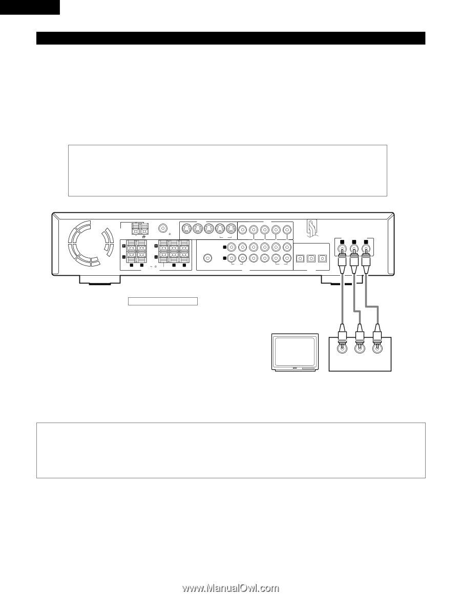
ENGLISH (5) Connecting to a TV or Monitor Equipped with Component Input Connectors. • When making connections, also refer to the operating instructions of the other components. • The video signals input to the VIDEO input (yellow) and S-Video input jacks are not output to the color difference (component) video jacks. Color component output connectors (CR, CB and Y) The red (CR), blue (CB) and brightness (Y) signals are output independently, achieving more faithful reproduction of the colors. • The color component input connectors may be marked differently on some TVs or monitors (PR, PB and Y/R- Y, B-Y and Y/CR, CB and Y, etc.). For details, refer to the TV's operating instructions. S VIDEO VIDEO LOOP ANT. FM COAX. 75 MON.OUT IN IN AM TV/DBS V.AUX R L IMPEDANCE 6 16 FRONT CENTER SPEAKER SYSTEMS R L SURROUND PRE OUT SUB WOOFER IN OUT MON.OUT VCR IN OUT IN IN L R CDR/ TAPE TV/DBS AUDIO V.AUX IN OUT VCR IN IN OUT TV/DBS V.AUX (OPTICAL) DIGITAL COMPONENT VIDEO OUT Y CB CR Connecting a monitor TV MONITOR OUT jack • Connect the TV's color difference (component) video input jacks (COMPONENT VIDEO INPUT) to the COMPONENT MONITOR OUT jack using 75 Ω/ohms coaxial video pinplug cords. Y CB CR COMPONENT VIDEO IN NOTES: • Use the three commercially available video cords to connect the ADV-700's color component output connectors to the TV or monitor. • Set the "TV TYPE" in "VIDEO SETUP" in "DVD SETUP" to comply with your TV's video format. When the TV is NTSC formated set to NTSC. 12
-
 1
1 -
2
-
3
-
4
-
5
-
6
-
 7
7 -
 8
8 -
 9
9 -
 10
10 -
 11
11 -
 12
12 -
 13
13 -
 14
14 -
 15
15 -
 16
16 -
 17
17 -
18
-
19
-
20
-
21
-
22
-
23
-
24
-
25
-
26
-
27
-
28
-
29
-
30
-
31
-
32
-
33
-
34
-
35
-
36
-
37
-
38
-
39
-
40
-
41
-
42
-
43
-
44
-
45
-
46
-
47
-
48
-
49
-
50
-
51
-
52
-
53
-
54
-
55
-
56
-
57
-
58
-
59
-
60
-
61
-
62
-
63
-
64
-
65
-
66
-
67
-
68
-
69
-
70
-
71
-
72
-
73
-
74
-
75
-
76
-
77
-
78
-
79
-
80
-
81
-
82
-
83
-
84
-
85
-
86
-
87
-
88
-
89
-
90
-
91
-
92
-
93
-
94
-
95
-
96
-
97
-
98
-
99
-
100
-
101
-
102
-
103
-
104
-
105
-
106
-
107
-
108
-
109
-
110
-
111
-
112
-
113
-
114
-
115
-
116
-
117
-
118
-
119
-
120
-
121
-
122
-
123
-
124
-
125
-
126
-
127
-
128
-
129
-
130
-
131
-
132
-
133
-
134
-
135
-
136
-
137
-
138
-
139
-
140
-
141
-
142
-
143
-
144
-
145
-
146
-
147
-
148
-
149
-
150
-
151
-
152
-
153
-
154
-
155
-
156
-
157
-
158
-
159
-
160
-
161
-
162
-
163
-
164
-
165
-
166
-
167
-
168
 |
 |