Epson 890N Service Manual - Page 7

Disassembly and Assembly, Adjustment, Maintenance, Appendix - fx 890 ribbon

Page 7 highlights

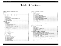
EPSON FX-890/2190 3.2.11 Electrical Noise 62 3.2.12 Fatal Error 63 3.3 Troubleshooting for Individual Units 64 3.3.1 Main Component Checking Point 64 Chapter 4 Disassembly and Assembly 4.1 Overview ...66 4.1.1 Disassembly Precautions 66 4.1.2 Tools and Instruments 66 4.1.3 Service Check After Repair 67 4.1.3.1 Abbreviations for Small Parts 68 4.2 Main Components Disassembly 69 4.2.1 Pre-disassembly Procedures 70 4.2.2 Upper Housing 72 4.2.3 C524MAIN Board 74 4.2.4 C524PSB/PSE/PSH Board 76 4.3 Printer Mechanism Disassembly 77 4.3.1 Printhead 77 4.3.2 HP (Home Position) Detector 78 4.3.3 Platen ...79 4.3.4 Printer Mechanism 80 4.3.5 CR Motor 81 4.3.6 PF Motor 83 4.3.7 PF Gear Train 84 4.3.8 PG (Platen Gap) Detector 86 4.3.9 Release Detector 86 4.3.10 Front PE (Paper End) Detector 87 4.3.11 Rear PE Detector 87 4.3.12 Carriage Assembly 88 4.3.13 Rear Paper Guide Assembly 90 4.3.14 Ribbon Drive (RD) Assembly 92 Chapter 5 Adjustment 5.1 Adjustment Overview 94 5.1.1 Required Adjustment 94 5.1.2 Adjustment Tools 94 5.2 Adjusting and Resetting the Printer 95 Revision B 5.2.1 Platen Gap Adjustment 95 5.3 Adjustment Program 97 5.3.1 Preparation 97 5.3.1.1 System Requirement 97 5.3.1.2 Installation 97 5.3.1.3 Running the Program 97 Chapter 6 Maintenance 6.1 Overview ...99 6.1.1 Preventive Maintenance 99 6.2 Lubrication ...100 Chapter 7 Appendix 7.1 Connector Summary 105 7.2 Electric Circuit Diagrams 108 7.3 Exploded Diagrams 114 7.4 Parts List ...122 7

  • 1
  • 2
  • 3
  • 4
  • 5
  • 6
  • 7
  • 8
  • 9
  • 10
  • 11
  • 12
  • 13
  • 14
  • 15
  • 16
  • 17
  • 18
  • 19
  • 20
  • 21
  • 22
  • 23
  • 24
  • 25
  • 26
  • 27
  • 28
  • 29
  • 30
  • 31
  • 32
  • 33
  • 34
  • 35
  • 36
  • 37
  • 38
  • 39
  • 40
  • 41
  • 42
  • 43
  • 44
  • 45
  • 46
  • 47
  • 48
  • 49
  • 50
  • 51
  • 52
  • 53
  • 54
  • 55
  • 56
  • 57
  • 58
  • 59
  • 60
  • 61
  • 62
  • 63
  • 64
  • 65
  • 66
  • 67
  • 68
  • 69
  • 70
  • 71
  • 72
  • 73
  • 74
  • 75
  • 76
  • 77
  • 78
  • 79
  • 80
  • 81
  • 82
  • 83
  • 84
  • 85
  • 86
  • 87
  • 88
  • 89
  • 90
  • 91
  • 92
  • 93
  • 94
  • 95
  • 96
  • 97
  • 98
  • 99
  • 100
  • 101
  • 102
  • 103
  • 104
  • 105
  • 106
  • 107
  • 108
  • 109
  • 110
  • 111
  • 112
  • 113
  • 114
  • 115
  • 116
  • 117
  • 118
  • 119
  • 120
  • 121
  • 122
  • 123
  • 124
  • 125
  • 126
  • 127
  • 128
  • 129

EPSON FX-890/2190
Revision B
7
3.2.11 Electrical Noise
.......................................................................................
62
3.2.12 Fatal Error
...............................................................................................
63
3.3 Troubleshooting for Individual Units
.............................................................
64
3.3.1 Main Component Checking Point
............................................................
64
Chapter 4 Disassembly and Assembly
4.1 Overview
............................................................................................................
66
4.1.1 Disassembly Precautions
..........................................................................
66
4.1.2 Tools and Instruments
...............................................................................
66
4.1.3 Service Check After Repair
......................................................................
67
4.1.3.1 Abbreviations for Small Parts
...........................................................
68
4.2 Main Components Disassembly
......................................................................
69
4.2.1 Pre-disassembly Procedures
.....................................................................
70
4.2.2 Upper Housing
..........................................................................................
72
4.2.3 C524MAIN Board
....................................................................................
74
4.2.4 C524PSB/PSE/PSH Board
.......................................................................
76
4.3 Printer Mechanism Disassembly
.....................................................................
77
4.3.1 Printhead
...................................................................................................
77
4.3.2 HP (Home Position) Detector
...................................................................
78
4.3.3 Platen
........................................................................................................
79
4.3.4 Printer Mechanism
....................................................................................
80
4.3.5 CR Motor
..................................................................................................
81
4.3.6 PF Motor
...................................................................................................
83
4.3.7 PF Gear Train
...........................................................................................
84
4.3.8 PG (Platen Gap) Detector
.........................................................................
86
4.3.9 Release Detector
.......................................................................................
86
4.3.10 Front PE (Paper End) Detector
...............................................................
87
4.3.11 Rear PE Detector
....................................................................................
87
4.3.12 Carriage Assembly
..................................................................................
88
4.3.13 Rear Paper Guide Assembly
...................................................................
90
4.3.14 Ribbon Drive (RD) Assembly
................................................................
92
Chapter 5 Adjustment
5.1 Adjustment Overview
......................................................................................
94
5.1.1 Required Adjustment
................................................................................
94
5.1.2 Adjustment Tools
......................................................................................
94
5.2 Adjusting and Resetting the Printer
...............................................................
95
5.2.1 Platen Gap Adjustment
.............................................................................
95
5.3 Adjustment Program
.......................................................................................
97
5.3.1 Preparation
................................................................................................
97
5.3.1.1 System Requirement
.........................................................................
97
5.3.1.2 Installation
.........................................................................................
97
5.3.1.3 Running the Program
........................................................................
97
Chapter 6 Maintenance
6.1 Overview
............................................................................................................
99
6.1.1 Preventive Maintenance
...........................................................................
99
6.2 Lubrication
......................................................................................................
100
Chapter 7 Appendix
7.1 Connector Summary
......................................................................................
105
7.2 Electric Circuit Diagrams
..............................................................................
108
7.3 Exploded Diagrams
........................................................................................
114
7.4 Parts List
.........................................................................................................
122