Epson Endeavor User Manual - Page 53
Be careful not to bend the jumper pins or damage any, gently move it to the desired position.
 |
View all Epson Endeavor manuals
Add to My Manuals
Save this manual to your list of manuals |
Page 53 highlights
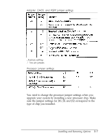
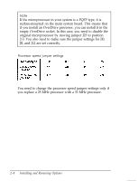
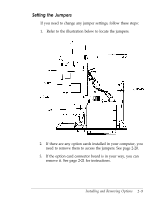
4. A jumper's setting is determined by where the jumper is placed on the pins. A two pin jumper either connects both pins (on) or sits on just one of the pins (off), as illustrated below. ON OFF For three pm jumpers, the jumper connects pin 1 and the middle pin (position l-2) or pin 3 and the middle pin (position 2-3), as shown below. (In the off position, a three pin jumper sits on only one of the end pins.) To move a jumper from one position to the other, use needle-nose pliers or tweezers to pull it off its pins and gently move it to the desired position. Caution Be careful not to bend the jumper pins or damage any surrounding components on the main system board. 5. If you removed the option card connector board, replace it now. See page 2-22 for instructions. 6. Replace any option cards you removed. See page 2-16 for instructions. 2-20 Installing and Removing Options
-
 1
1 -
2
-
3
-
4
-
5
-
6
-
7
-
8
-
9
-
10
-
11
-
12
-
13
-
14
-
15
-
16
-
17
-
18
-
19
-
20
-
21
-
22
-
23
-
24
-
25
-
26
-
27
-
28
-
29
-
30
-
31
-
32
-
33
-
34
-
35
-
36
-
37
-
38
-
39
-
40
-
41
-
42
-
43
-
44
-
45
-
46
-
47
-
 48
48 -
 49
49 -
 50
50 -
 51
51 -
 52
52 -
 53
53 -
 54
54 -
 55
55 -
 56
56 -
 57
57 -
 58
58 -
59
-
60
-
61
-
62
-
63
-
64
-
65
-
66
-
67
-
68
-
69
-
70
-
71
-
72
-
73
-
74
-
75
-
76
-
77
-
78
-
79
-
80
-
81
-
82
-
83
-
84
-
85
-
86
-
87
-
88
-
89
-
90
-
91
-
92
-
93
-
94
-
95
-
96
-
97
-
98
-
99
-
100
-
101
-
102
-
103
-
104
-
105
-
106
-
107
-
108
-
109
-
110
-
111
-
112
-
113
-
114
-
115
-
116
-
117
-
118
-
119
-
120
-
121
-
122
-
123
-
124
-
125
-
126
-
127
-
128
-
129
-
130
-
131
-
132
-
133
-
134
-
135
-
136
-
137
-
138
-
139
-
140
-
141
-
142
-
143
-
144
-
145
-
146
-
147
-
148
-
149
-
150
-
151
-
152
-
153
-
154
-
155
-
156
-
157
-
158
-
159
-
160
-
161
-
162
-
163
-
164
-
165
-
166
-
167
-
168
-
169
-
170
-
171
-
172
-
173
-
174
-
175
-
176
-
177
-
178
-
179
-
180
-
181
-
182
-
183
-
184
-
185
-
186
-
187
-
188
-
189
-
190
-
191
-
192
-
193
-
194
-
195
-
196
-
197
 |
 |
