Epson MX-82 F/T User Manual
Epson MX-82 F/T Manual
 |
View all Epson MX-82 F/T manuals
Add to My Manuals
Save this manual to your list of manuals |
Epson MX-82 F/T manual content summary:
- Epson MX-82 F/T | User Manual - Page 1
MX-82 EPSON DOT MATRIX PRINTER Operation Manual MX MX-82 F/T EPSON P8190027-2 - Epson MX-82 F/T | User Manual - Page 2
Copyright 0 1981 by EPSON, Shinshu Seiki Co., Ltd. Nagano, Japan "All rights reserved" *The contents of this manual are subject to change without notice. - Epson MX-82 F/T | User Manual - Page 3
6.3 Column layout on fanfold paper 14 6.4 Top of form position setting 14 7. Gap Adjustment 15 8. Power Connection 16 INSTALLATION OF MX-82 F/T 17 1. Unpacking ...17 1.1 Unpacking steps 17 1.2 Repacking steps 17 2. Counting the Parts 18 3. Installation of the Printer 19 4. Cartridge Ribbon - Epson MX-82 F/T | User Manual - Page 4
41 5.1 Setting of DIP switch 1 45 5.2 Setting of DIP switch 2 46 5.3 Coding tables 47 6.4 Setting sequence of funcional specifications 48 WHAT IS THE MX-82 53 1. What is a Dot Matrix Printer 53 2. Definition of Some Terms Often Used 56 3. Control Codes in the Text Mode 58 4. Control Codes in - Epson MX-82 F/T | User Manual - Page 5
LIST OF FIGURES Fig. 1 EPSON MX-82 and MX-82 F/T Dot Matrix Printer 1 Fig. 2 Contents of Carton 4 Fig. 3 Laying Printer on Firm Surface 5 Fig. 4 Assembly Tools 6 Fig. 5 Removal of Shipping Screws 6 Fig. 6 Removal of Printer - Epson MX-82 F/T | User Manual - Page 6
. 49 Flowchart of Paper Out Status Release Procedure 39 Fig. 50 Removing Manual Paper Feed Knob 41 Fig. 51 Loosening All 4 Screws 42 Fig. 85 Fig. A2-1 Parallel Interface Timing 89 Fig. A3-1 Connection of MX-82, MX-82 F/T to Computers 94 LIST OF TABLES Table 1 Interface Signals in Paper-Out - Epson MX-82 F/T | User Manual - Page 7
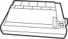
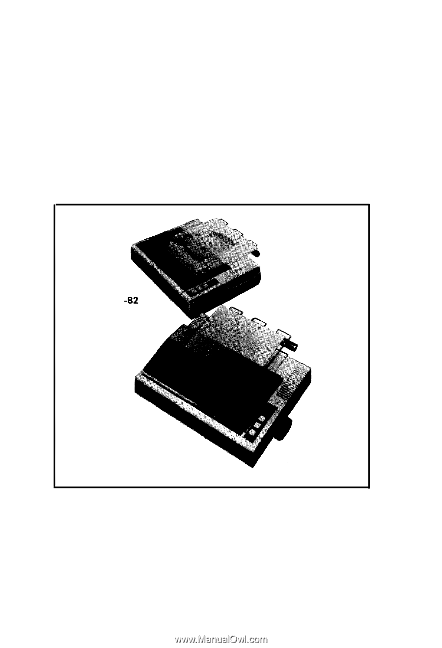
feed type, a friction and adjustable sprocket feed type called "MX-82 F/T" is also available. In this manual, installation of MX-82 and MX-82 F/T will be described individually and then the operation which is common to both will be described. Fig. 1 EPSON MX-82 and MX-82 F/T Dot Matrix Printer -1- - Epson MX-82 F/T | User Manual - Page 8
2. Characteristics The MX-82 and MX-82 F/T have been designed as a printer with versatile functions to meet a wide range of applications from small business to home uses and even for hobbies. The - Epson MX-82 F/T | User Manual - Page 9
repair, storage, etc.) NOTE: It is recommended that all original packing materials be saved for reuse in case the MX-82 requires reshipment in the future. 2. Counting Parts The MX-82 and standard accessories are as shown in Fig.2. Upon unpacking, if you notice any listed contents missing or evident - Epson MX-82 F/T | User Manual - Page 10
L 2. Separato 3. Cartridge Ribbon- * 1. MizizGkL (European Type) 1. MX-82 1 2. Separator 1 3. Cartridge Ribbon 1 4. Power (Only European Type 220/240V) 1 5. MX-82 Operation Manual 1 Fig. 2 Contents of Carton - Epson MX-82 F/T | User Manual - Page 11
3. Installation of the Printer (1) Operating site selection When installing the MX-82, observe the following instructions. (a) Place the Printer on a bench, tabletop or any other convenient flat surface with enough room for the separator in the back of the Printer. Your - Epson MX-82 F/T | User Manual - Page 12
with a protective paper inserted between the inner and outer paper guides to protect the paper end detector from damage due to shocks or vibrations during transportation. Before using the Printer, be sure to remove this paper. If the MX-82 is to be reshipped, remember to return it to the original - Epson MX-82 F/T | User Manual - Page 13
0 If the printer lid is an obstacle when removing the shipping screws, be sure to take off the printer lid by observing the following steps. Rough or careless handling of the printer lid may result in damage to, or even breakage of, its hinges. STEP 1. Stand the printer lid upright. 2. - Epson MX-82 F/T | User Manual - Page 14
4. Cartridge Ribbon Setting EPSON's Cartridge Ribbon is compact, long-lasting, and very easy to set and remove. Furthermore, you have no need to soil your fingers in handling it. - Epson MX-82 F/T | User Manual - Page 15
Fig. 9 Cartridge Ribbon Setting NOTES 1: Incorrect setting of the ribbon may cause it to come off. 2: Confirm that the ribbon is neither twisted nor creased and that the cartridge is set properly. I Ribbon kRibbon Mask Incorrect Incorrect Correct I Fig. 10 Examples of Correct and Incorrect - Epson MX-82 F/T | User Manual - Page 16
Fig. 11 Separator installation 6. Paper Loading 6.1. Loading of fanfold paper The MX-82 Printer accommodates fanfold paper from 4" to 10" in width. To load the and detach it from the platen. 3. Confirm that the paper guide roller is at the center of the sprocket shaft. If not, set it at - Epson MX-82 F/T | User Manual - Page 17
Fig. 12 Insertion of Fanfold Paper 5. Push the paper into the insertion slot between the paper guides at the rear part of the printer mechanism. NOTE: Be sure to pass the paper beneath the upper paper guide. 6. After the leading edge of the paper has emerged from the Printer, pull it out - Epson MX-82 F/T | User Manual - Page 18
7. Raise the two sprocket lock levers to loosen, and adjust the sprocket pin position to the paper width. (See Fig. 13) Paper Fig. 13 Raising of Sprocket Lock Levers 8. Engage the paper feed holes of the paper on the feeding pins, push the scale back into position, and adjust the tension of the - Epson MX-82 F/T | User Manual - Page 19
9. Put the printer lid on the Printer. Fig. 15 Printer with Fanfold Paper Set Completely NOTE: When the MX-82 is to be used on a desk or a bench, arrangement of the fanfold paper in parallel with the MX-82 as shown below will permit the paper to be folded in an accordion style. I I_- Fig - Epson MX-82 F/T | User Manual - Page 20
When fanfold paper of from 4" to 10" in width is supplied with the MX-82 the graduations on the scale can be used as the indexes of print column the power switch is turned on. Namely, adjust the paper position by the manual paper feed knob so that the required line position (i.e., the point at which - Epson MX-82 F/T | User Manual - Page 21
Fig. 17 Top of Form 7. Gap Adjustment The adjustment of a gap between the head nose and the platen is used to adjust the printing pressure as well as to suit the paper of the different thickness. (1) Move the head adjusting lever (located on the left frame of the Printer) forward or backward to - Epson MX-82 F/T | User Manual - Page 22
8. Power Connection The EPSON MX-82 Dot Matrix Printer is capable of operating on the following three types of AC power. (1) 115V AC, 60 Hz (2) 220V AC, 50 Hz (3) 240V AC, 50 Hz Before connecting the MX-82 to a power source, make certain of the primary AC rating from the label located on the chassis - Epson MX-82 F/T | User Manual - Page 23
present, notify the carrier immediately. 1.1 Unpacking steps Unpacking steps are as follows: STEP 1. Open the carton. 2. Remove accessories. 3. Remove the MX-82 F/T by holding its underside and lifting it straight up with the packing materials attached. 4. Place the Printer with the packing material - Epson MX-82 F/T | User Manual - Page 24
the store where you purchased the MX-82 F/T as soon as possible. Dot Matrix Printer (European Type) 5. Operation Manual 1. MX-82 F/T 1 2. Separator 1 3. Cartridge Ribbon 1 4. Power Cord (Only European Type 220/240V) 1 5. MX-82 F/T Operation Manual 1 Fig. 19 Contents of Carton -18 - Epson MX-82 F/T | User Manual - Page 25
3. Installation of the Printer (1) Operating site selection When installing the MX-82 F/T, observe the following instructions. (a) Place the Printer on a bench, tabletop or any other convenient flat surface with enough room for the separator in the back of the Printer. Your - Epson MX-82 F/T | User Manual - Page 26
with a protective paper inserted between the inner and outer paper guides to protect the paper end detector from damage due to shocks or vibrations during transportation. Before using the Printer, be sure to remove this paper. If the MX-82 F/T is to be reshipped, remember to return it to the - Epson MX-82 F/T | User Manual - Page 27
0 If the printer lid is an obstacle when removing the shipping screws, be sure to take off the printer lid by observing the following steps. Rough or careless handling of the printer lid may result in damage to, or even breakage of its hinges. STEP1. Stand the printer lid upright. 2. - Epson MX-82 F/T | User Manual - Page 28
4. Cartridge Ribbon Setting EPSON's Catridge Ribbon is compact, long-lasting, and very easy to set and remove. Furthermore, you have no need to soil your fingers in handling it. - Epson MX-82 F/T | User Manual - Page 29
NOTES: 1. Incorrect setting of the ribbon may cause it to come off. (See Fig. 26) 2. Confirm that the ribbon is neither twisted nor creased and that the cartridge is set properly. .-Ribbon IRibbon Mask Incorrect Incorrect Correct Fig. 26 Examples of Correct and Incorrect Ribbon Setting 5. - Epson MX-82 F/T | User Manual - Page 30
6. Mounting and Dismounting of Tractor Unit The tractor unit of the MX-82 F/T is detachable. If it is an obstacle when using roll paper, it can be taken out as follows; STEP 1. Release the lock levers of the - Epson MX-82 F/T | User Manual - Page 31
Paper Loading 7.1 Fanfold paper 7.1.1 Loading of fanfold paper The MX-82 F/T Printer accommodates fanfold paper from 4" to 10" in width. of the Printer to detach the scale from the platen. 4. Confirm that the paper guide roller is at the center of the sprocket shaft. If not, set it at the center of - Epson MX-82 F/T | User Manual - Page 32
8. Raise the two sprocket lock levers to loosen, and adjust the sprocket pin position to the paper width. (See Fig. 31) ket Lock Lever I Fig. 31 Raising of Sprocket Lock Levers 9. Engage the paper feed holes of the paper on the feeding pins, push the scale back into position, and adjust the - Epson MX-82 F/T | User Manual - Page 33
the Printer. (See Fig. 33) Fig. 33 Printer with Fanfold Paper Set Completely NOTE: When the MX-82 F/T is to be used on a desk or a bench, arrange- ment of the fanfold paper in parallel with the MX-82 F/T as shown below will permit the paper to be folded in an accordion style. Fig. 34 - Epson MX-82 F/T | User Manual - Page 34
power switch is turned on. Namely, adjust the paper position by the manual paper feed knob so that the required line position (i.e., the point at In case of feeding one page of fanfold paper by operating the MX-82 F/T by the input of FF code, the abovementioned adjustment is effective. Matchmark \J: fi - Epson MX-82 F/T | User Manual - Page 35
holder EPSON offers the roll paper holder as an optional accessory for the MX-82 F/T. 7.2.2 Loading of roll paper The MX-82 F/T guide. 2. Two-ply roll paper is not recommended for use. 7. Lock the release lever and push the scale back into the original position. 8. While turning the manual - Epson MX-82 F/T | User Manual - Page 36
Paper (2) Release Lever Manual Paper Feed Knob Fig. 38 Loading of Roll Paper (3) 7.3 Cut paper sheet 7.3.1 Loading of cut paper sheet The MX-82 F/T accommodates cut paper the platen. (See Fig. 39) 4. Confirm that the paper guide roller is at the center of the sprocket shaft. If not, set it at the - Epson MX-82 F/T | User Manual - Page 37
Release Lever Fig. 39 Loading of Cut Paper Sheet 6. Lock the release lever. 7. While turning the manual paper feed knob clockwise, confirm that the paper advances straight up. (See Fig. 40) Manual Paper Feed Knob Fig. 40 Adjustment of Inserted Paper Position If not, adjust the inserted paper - Epson MX-82 F/T | User Manual - Page 38
Fig. 41 Alignment of Side Edges b) If the cut paper sheet or form is not long enough to align the side edges, align the top edge of the paper with the form position setting mark on the tractor unit. (See Fig. 42) Fig. 42 Form Position Setting Mark The print area on the cut paper sheet is shown in - Epson MX-82 F/T | User Manual - Page 39
Letter Size Paper t-I+y---..- A4 Size Paper 1. Fig. 44 Setting of Cut Paper Sheet NOTES: 1. The Paper End Detector function may be disabled under software control (ESC 8; refer to page 66 provided printing is left off within 7.5 mm from the paper bottom edge). 2. If the paper is set on the line - Epson MX-82 F/T | User Manual - Page 40
paper sheets is used, be sure that no characters are printed within the area two lines each above and below the perforation. 8. Power Connection The EPSON MX-82 F/T Dot Matrix Printer is capable of operating on the following three types of AC power. (1) 115V AC, 60Hz (2) 220V AC, 50 Hz (3) 240V AC - Epson MX-82 F/T | User Manual - Page 41
Head Adjusting Le BBackward M Forward @I Head Adjusting Lever (Side view) Fig. 46 Gap Adjustment -35- - Epson MX-82 F/T | User Manual - Page 42
OPERATION 1. Switches and Indicators There are three switches and four indicators (green LED's) on the control panel and one power switch on the right side of the Printer case. In this section, panel operating procedures are covered in sufficient detail for the user to become familiarized with the - Epson MX-82 F/T | User Manual - Page 43
FF SW: (Form Feed) LF SW: (Line Feed) When this switch is depressed once, the paper is advanced vertically to the next Top of Form position. This switch must be depressed while the Printer is OFF-LINE. Otherwise, the form feed operation will not be carried out. The Top of Form position is - Epson MX-82 F/T | User Manual - Page 44
1.3 Printer initial check Take the following steps and become familiar with the Printer. Interface cable 7START Turn on POWER Check the LF & FF Contact yEoPuSrOnNeadreeas,ter. qg&&x+ Fig. 48 Printer Initial Check -38- - Epson MX-82 F/T | User Manual - Page 45
code ((07)20H). (See page 66 for the BEL code.) 3. Paper End Detector (1) When the paper end detector (a reed switch located on the paper guide) detects that the paper is nearly exhausted, the signals on the interface connector change to the following status, and the printing operation stops. Table - Epson MX-82 F/T | User Manual - Page 46
become invalid hardwarewise. (b) Enter control code "ESC 8" and the paper end detecting function will become invalid softwarewise. 4. Self-Test The MX-82, MX-82 F/T has a self-test (self-diagnostic) function to check the following. (1) Print head operation and printing quality. (2) Operation of the - Epson MX-82 F/T | User Manual - Page 47
static electricity which might be charged in your body, or it may cause damages to internal electronic parts such as LSl's, IC's, etc. Remove the manual paper feed knob (black knob on the right side) by pulling it straight out, with firm but steady force. (See Fig. 50) Fig. 50 Removing - Epson MX-82 F/T | User Manual - Page 48
Turn the printer upside down on a soft surface. With a Phillips type screwdriver, completely loosen all 4 screws. (See Fig. 51) Place tape over the 4 holes so the screws won't fall off when you tip the printer right side up. Fig. 51 Loosening All 4 Screws Tip the printer right side up again. Gently - Epson MX-82 F/T | User Manual - Page 49
a control panel. (See Fig. 53) Construction of the Printer Transformer & Control panel I I Transformer & filter circuit board ter mechanism MX-82 or MX-82 F/T Dot Matrix Printer Driver circuit board 7i 1 (cd female) HMTP board (Control circuit board) / J Controller Fig. 53 Construction - Epson MX-82 F/T | User Manual - Page 50
DIP swit$h 2 VIP switch 1 Fig. 54 Location of DIP Switches -I Position the printer as shown in Fig. 53. There are two "DIP' (DUAL IN-LINE PACKAGE) switches in the HMTP board. (See Fig. 54) The switches set to the left are ON... to the right are OFF. (See Fig. 55) SW 1 Fig. 55 Setting DIP Switches - Epson MX-82 F/T | User Manual - Page 51
5.1 Setting of DIP Switch No. 1 The DIP switch No. 1 consists of the following 8 pins. A summary of the functions of the respective DIP switch pins and their preset conditions at the time of shipment are shown in Table 2. Table 2 Functions and Conditions of DIP Switch No. 1 (1) SW1-1: Setting this - Epson MX-82 F/T | User Manual - Page 52
. (2) SW2-3: This pin is used to fix AUTO FEED XT signal internally. (Refer to the explanation of control code "CR" in paragraph 3.1 (1) "WHAT IS THE MX-82") This signal line is wired ORed with the pin No. 14 of the interface connector. Therefore, to control the pin No. 14 externally through TTL - Epson MX-82 F/T | User Manual - Page 53
5.3 Coding Tables Appendix 4 shows all available codes when the Printer is set for operation with standard coding by setting the DIP switch pins 1-7, 2-1 and 2-2 to all ON position, Table 5 shows International Character Set Designation according to the combination of the DIP switch setting. Table 5 - Epson MX-82 F/T | User Manual - Page 54
5.4 Setting Sequence of Functional Specifications The MX-82, MX-82 F/T have a choice of various functional specifications such as amount of line spacing, form length per page, number of columns per line, automatic skip-over perforation. - Epson MX-82 F/T | User Manual - Page 55
YES 12 inch ESCCtn ESCC+O+m The skip-over perforation function, if previously set, will be reset at this point. Fig. 57 Setting Form Length per Page -49- - Epson MX-82 F/T | User Manual - Page 56
(7Power ON 96 columns Normal Emphasized SI or 4 - ESCSI print print 0DC2 I Fig. 58 Setting Number of Columns per Line -50- - Epson MX-82 F/T | User Manual - Page 57
l-inch skip-over YES perforation function not provided NO l-inch skip-over perforation function provided i-1ESCN+n ESC 0 t Fig. 59 Setting Skip-over Perforation Function -51- - Epson MX-82 F/T | User Manual - Page 58
be classified by categories such as impact or non-impact printing method, line or serial printing method and so on. Broadly speaking, the EPSON MX-82 belongs to the following categories. * Impact printer * Dot matrix printer * Serial printer with one line buffer * Receive only printer (This printer - Epson MX-82 F/T | User Manual - Page 59
it is one of the key features that the printer has. EPSON's MX-82 can control each needle programmably, expanding the ability of the printer to impact carbon, causing the character to be printed as a series of dots. Head guide I '2s= .cs- Dot wire Head movement - direction Dot Wire #l- 0.0.. -0 - Epson MX-82 F/T | User Manual - Page 60
have a switch or lever to change the line spacing (1/6" or 1/8"). The MX-82 also can do this of course. In addition, you can set it programmably image mode. On the other hand, with 1/6" line spacing, there is no problem even if upper case characters and lower case ones are mixed in a message. - Epson MX-82 F/T | User Manual - Page 61
must be programmed to acknowledge the code used in computer systems. The MX-82 has 96 character set and control codes. In addition, it has an bit data bus line. (2) Escape codes In a lot of control codes that the MX-82 has, you might be confused by the word "ESCAPE". Some alphabetical letters and - Epson MX-82 F/T | User Manual - Page 62
"ESCAPE" codes used in the MX-82 should not be confused with the escape key which some computers have. So be familiar with EPSON'S control codes. (3) "+" symbol the Bit Image Mode is covered in the following section. The MX-82 has been designed as a terminal unit capable of various software controls - Epson MX-82 F/T | User Manual - Page 63
(3) Character designation codes SO, ESC SO, DC 4... Enlarged printing SI, ESC SI, DC 2... Condensed printing ESC E, ESC F... Emphasized printing ESC R... International character set (4) Other codes DC 1, DC 3... Selection or deselection of the printer ESC 8, ESC 9... Selection or deselection of the - Epson MX-82 F/T | User Manual - Page 64
(3) VT (Vertical Tabulation) When the VT code is input, all data preceding this code is printed and the vertical tabulation is made to a predetermined line position set by "ESC B" (up to 8 positions). If no vertical tab position is set by ESC B, the VT code behaves like the LF code. Therefore, the - Epson MX-82 F/T | User Manual - Page 65
r 1. In case of 5th. 10th and 219 columns. [DATA] -1 H H Hm ABC m DEF lHTj GHl [PRINT] bg JKL a (LFI AEC DEF GHI JKL 2. In case of lack of stop position. [DATAI -1 H H m ABC m DEF m GHI m JKL [PRINT] @Ja ABC DEF GHI JKL 3. In case of character data transferring over next - Epson MX-82 F/T | User Manual - Page 66
(4) ESC A + n (for setting amount of line spacing) This code specifies the amount of line spacing in the Line Feed, provided that (n)o must satisfy the condition: 1 s (n)b Z 85 (Decimal). "n" - 1 is equivalent to 1/72 inch paper advancement. Since the distance between any two dot wires of the print - Epson MX-82 F/T | User Manual - Page 67
(5) ESC 0 input of the ESC 0 causes the subsequent line spacing to be set at 1/8 inch. (6) ESC2 Input of the ESC 2 causes the subsequent line spacing to be set at either 1/6 inch or 1/8 inch depending on the initial set condition of the DIP switch pin 1-1. (7) VT (Vertical Tabulation) See paragraph - Epson MX-82 F/T | User Manual - Page 68
(9) FF (Form Feed) See paragraph 3.1 (4) above. (10) ESC C + n (for setting a form length) ESC C + n (n + 0), ESC C + [O]H + m (for setting form length) The "ESC C + n" codes specifies the form length which is determined by the number of lines (n: 1 s (n)n $ 127 where the value of "n" is a positive - Epson MX-82 F/T | User Manual - Page 69
(Example) 3-line skip-over perforation [PRINT] BQBBc~!:4BQ BBBQ(1!BBQ mx!Bc~!:Jm! (at 1/6 inch line spacing) Skip for 3 lines End of previous page Top of form position Beginning of next page (12) ESC 0 This code - Epson MX-82 F/T | User Manual - Page 70
(2) SI (Shift In) (for condensed characters) When the SI code is input, all data that follows it will be printed out in condensed characters. This code is cancelled by the input of "DC 2" code. The SI code can be input at any column position on a line, but all characters/symbols on the line - Epson MX-82 F/T | User Manual - Page 71
(7) ESC E (for emphasized characters) The ESC E code causes the Printer to print emphasized characters. Emphasized printing gives the character stronger impression on the paper. This code can be input in any column position on a line, but all characters on the line containing ESC E code are printed - Epson MX-82 F/T | User Manual - Page 72
3.4 Other codes (1) DC 1 (Device Control 1) The DC 1 code places the Printer in the Selected state. It enables the Printer to receive data. With the Printer in the Selected state, if the DC 1 code is input during data transfer, all data stored before the DC 1 code is ignored. (2) DC 3 (Device - Epson MX-82 F/T | User Manual - Page 73
of this code in the Text Mode causes the Printer's operation mode to be converted from Text to Normal-density Bit Image. Refer to paragraph 4.1, section 4, for by-193 screen matrix. As well as the latter "APPLE II", the MX-82 has no character generated graphics but allow you to control all the 8 - Epson MX-82 F/T | User Manual - Page 74
4.1 Normal-density bit image mode setting by ESC K + nl + nz To convert the printer's operation mode from Text to Normal-density Bit Image, the "ESC K + nl + nz" code must be input. (Here, the sign "+" is inserted for - Epson MX-82 F/T | User Manual - Page 75
Printing Text data A (Ex. 3) Input data Bit-image data B Text data C 576 bit-image positions Bit-image data D nz. ni t I Printing (Ex. 4) Bit image data transfer by standard BASIC program To check for proper coversion to the Normal-density Bit Image mode, execute the following program. [ - Epson MX-82 F/T | User Manual - Page 76
imagemode setting by ESC L + nl + nz When the ESC (< 1 B> H) and L (< 4C > H) codes followed by data nc and n2 are input, the printer's operation mode is converted from Text to Dual-density Bit Image. The transfer sequence of bit image data is the same as with the ESC K (normal-density bit image - Epson MX-82 F/T | User Manual - Page 77
4.3 Relationship between data and dot wires Fig. 63 shows the relationship between the Bit Image data and the dot wires in the print head. You can control arbitrary 8 dot wires in the print head. LSB Input data Dot wire l - 04 l 0 .l 0 & NOTE: In the Bit Image mode, the 9th dot wire cannot be - Epson MX-82 F/T | User Manual - Page 78
4.4 How to obtain nl and n2 In the MX-82 Printer, you have to send the amount of data by nr + n2 in hexadecimal numbers following the ESC K or ESC L. If the amount of bit - Epson MX-82 F/T | User Manual - Page 79
4.5 Programming examples (1) Dual-density bit image printing Fig. 65 Example of Graphic Pattern Formation NOTE: The most significant bit (MSB) of the bit image data corresponds to the dot wire at the uppermost position. For example, to print a graphic data as shown in Fig. 65, a program such as - Epson MX-82 F/T | User Manual - Page 80
- Epson MX-82 F/T | User Manual - Page 81
density b) Dual density Fig. 66 Normal-Density and Dual-Density Modes NOTE: Print alignment under the friction feed. EPSON is carefully applying printer mechanisms of better quality for MX-82 F/T. However, due to the nature of friction feed in which paper may slip, it is not available to use - Epson MX-82 F/T | User Manual - Page 82
(4) Example of CRT screen dump hard copy This print example is made using APPLE II® computer and the demonstration diskette. Fig. 67 Examples of Bit Image Printing -76- - Epson MX-82 F/T | User Manual - Page 83
(5) Example of expression of brightness using the Bit Image Mode (Ex.) Expression of brightness using the bit image mode 4 5 6 (Ex.) Expression of dot density l a oe.*.a .. A: @*.*a @ mlleee o@m a . ee * *@* .o Data will be transmitted in order of H and then < 55 > H (8-dot line spacing - Epson MX-82 F/T | User Manual - Page 84
water solution. 2. Parts Replacement (1) General Owing to the sophisticated nature of the circuitry and mechanisms utilized in the MX-82, MX-82 F/T, operator's troubleshooting is logically obliged to be limited to certain easily recognizable symptoms and cures. If a Printer malfunction other than - Epson MX-82 F/T | User Manual - Page 85
1 Print Head Print Head Unit , Terminal Board Head Lock Lever Carnage Assembly Head Connector 'Be sure to hold this connector firmly lo pull the head cable out straight (Side View) 'Take hold of the cable at the point izicated b y ariows o and apply force in either of the directions indicated - Epson MX-82 F/T | User Manual - Page 86
48 19.9 159 Condensed Enlarged: 9.9 79 (8) MEDIA HANDLING Paper Feed: Adjustable sprocket pin feed (and/or friction feed for MX-82F/T) Paper Width Range: MX-82 MX-82 F/T Fanfold paper: 4" to 10" 4" to 10" (101.6mm to 254mm) (101.6mm to 254mm) Roll paper: 8.5" f 0.12" (215.9 f 3 mm - Epson MX-82 F/T | User Manual - Page 87
(13) POWER REQUIREMENT Voltage: 115V.60Hz 220/240V, 50 Hz Current: 1 Amp maximum Power Consumption: 100 VA maximum (14) PHYSICAL CHARACTERISTICS MX-82 MX-82F/T Height: 107 mm (4.2") 133 mm (5.2") Width: 374 mm (14.7") 374 mm (14.7") Depth: 305 mm (12.0") 305 mm (12.0") Weight - Epson MX-82 F/T | User Manual - Page 88
APPENDIX 1 Construction of MX-82 and MX-82 F/T The EPSON MX-82 and MX-82 F/T dot matrix printers consist of One complete rotation of the stepper motor corresponds to 1/3 inch paper advance. In the MX-82, MX-82 F/T printers the operator can select any paper feed length under software control. (3) - Epson MX-82 F/T | User Manual - Page 89
Fig. Al -1 Control Circuit Diagram - Epson MX-82 F/T | User Manual - Page 90
1.3 Power circuit The power circuit generates 5V DC for the logic circuit, and 24V DC to energize the solenoids of the print head and two stepper motors. 1.4 Printer initialization Printer initialization is accomplished in either of the two ways described below. (1) initialization takes place - Epson MX-82 F/T | User Manual - Page 91
9 X 2SD986 - HI D H: LFA 0 LFC 0 - LFA - LFD Fig. A1 -2 Driver Circuit Diagram -86- - Epson MX-82 F/T | User Manual - Page 92
APPENDIX 2 Parallel Interface Both the MX-82 and MX-82 F/T include a parallel interface as the standard equip- ment, and this paragraph describes the parallel interface. (1) Specifications (a) Data transfer rate: 1000 CPS (min.) (b) Synchronization: By externally - Epson MX-82 F/T | User Manual - Page 93
Table A2-1 (cont'd) ; Description 14 / - lmi In 15 - 16 - 17 - 16 - 19to30 - NC OV %nosas- - NC GND - This signal indicates that the printer is in the selected state. With this signal being at "LOW" level, the paper is automatically fed one line after printing. (The sig nal level - Epson MX-82 F/T | User Manual - Page 94
3. All interface conditions are based on TTL level. Both the rise and fall times of each signal must be less than 0.2 p.s. 4. Data transfer must not be carried out by ignoring the ACKNLG or BUSY signal. (Data transfer to this printer can be carried out only after confirming the ACKNLG signal or when - Epson MX-82 F/T | User Manual - Page 95
NOTES: 1. In Table A2-2, it is assumed that as soon as the Printer receives data, it sends back the ACKNLG signal, though this data is not stored in the print buffer. In this status, the Printer is waiting for the DC 1 code for normal entry. 2. In the above table, it is also assumed that no ERROR - Epson MX-82 F/T | User Manual - Page 96
I HNoex. . o , 2 3 4 5,I 61I 7 I 8'9!A - I 6 c D I"S( I . l-l Ic ' - Epson MX-82 F/T | User Manual - Page 97
APPENDIX 4 Character Fonts (Hex Code) 20 2-1 23 24 25 26 27 ti i i iJ 28 29 28 2c 20 2E 32 38 38 3c 3E 3F 42 46 48 49 4A 48 4c 40 4E A,.F 60 52 -92- - Epson MX-82 F/T | User Manual - Page 98
58 59 5A 50 5c 5D 5E 5F 69 69 6A 6B 6C 6D liiiil 73 . . 78 79 7A 78 7c 7D 7E NOTE: Numbers represent Hex. - 93 - - Epson MX-82 F/T | User Manual - Page 99
FRANCE 40 5B 5c 5D' 78 7c 7D 7E GERMANY 5B 5c 5D 70 liiiil 7D- 7E ENGLAND 23 DENMARK 5c 5D 78 70 SWEDEN 24 5c 5D 60 70 7c 7D 7E ITALY 58 5D 60 78 7c 7D 7E - Epson MX-82 F/T | User Manual - Page 100
SPAIN 23 55 5c 50 78 7c -96- - Epson MX-82 F/T | User Manual - Page 101
ESC 8 38 56 Deselects paper end detector. 66 ESC 0 4F 79 Releases skip-over perforation. 63 ESC Q 51 81 Sets a column length. 59 ESC R 52 82 Selects an international character set from among 65 - Epson MX-82 F/T | User Manual - Page 102
used properly. that is, in strict accordance with the manufacturer's instructions, may cause interference to radio and television reception. It has been Commission helpful: "How to ldentify and Resolve Radio-TV Interference Problems." This booklet is available from the US Government Printing Office. - Epson MX-82 F/T | User Manual - Page 103
AMERICA, INC. (LA) 3415 Kashiwa St. Torrance, Ca. 90505 Phone: (213)539-9140 Telex: 182412 EPSON DEUTSCHIAND GMBH Am Seestern 24 4000 Diisseldotf 11. F.R. Germany Phone: 0211-5961001 Telex: 8584786 EPSON U.K. LTD. Sherwood Howe 176 Northolt Road South Harrow HA2 OEB U.K. Phone: (01)422-5612 Telex
-
 1
1 -
 2
2 -
 3
3 -
 4
4 -
 5
5 -
 6
6 -
 7
7 -
8
-
9
-
10
-
11
-
12
-
13
-
14
-
15
-
16
-
17
-
18
-
19
-
20
-
21
-
22
-
23
-
24
-
25
-
26
-
27
-
28
-
29
-
30
-
31
-
32
-
33
-
34
-
35
-
36
-
37
-
38
-
39
-
40
-
41
-
42
-
43
-
44
-
45
-
46
-
47
-
48
-
49
-
50
-
51
-
52
-
53
-
54
-
55
-
56
-
57
-
58
-
59
-
60
-
61
-
62
-
63
-
64
-
65
-
66
-
67
-
68
-
69
-
70
-
71
-
72
-
73
-
74
-
75
-
76
-
77
-
78
-
79
-
80
-
81
-
82
-
83
-
84
-
85
-
86
-
87
-
88
-
89
-
90
-
91
-
92
-
93
-
94
-
95
-
96
-
97
-
98
-
99
-
100
-
101
-
102
-
103
 |
 |
MX-82
EPSON DOT MATRIX PRINTER
Operation Manual
MX
MX-82 F/T
EPSON
P8190027-2