Epson MX-82 F/T User Manual - Page 77
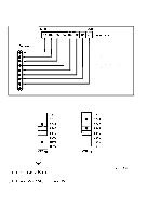
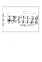
Fin. 63 Relationship, 3 Relationship between data and dot wires, between Data and Dot Wires
 |
View all Epson MX-82 F/T manuals
Add to My Manuals
Save this manual to your list of manuals |
Page 77 highlights
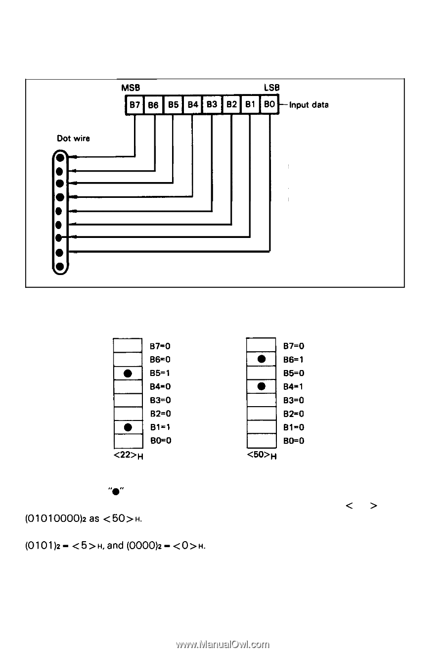
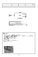
4.3 Relationship between data and dot wires Fig. 63 shows the relationship between the Bit Image data and the dot wires in the print head. You can control arbitrary 8 dot wires in the print head. LSB Input data Dot wire l - 04 l 0 .l 0 & NOTE: In the Bit Image mode, the 9th dot wire cannot be used. Fin. 63 Relationship between Data and Dot Wires If a bit is "1", the print head fires. If a bit is "0", the print head does not fire. For example, assume that data are given as follows; B7=0 B6=0 B5=1 B4=0 B3=0 B2=0 Bl-1 BO=O ,, 67=0 B6=1 B5=0 B4=1 B3=0 B2=0 Bl-0 BO=O ,, where a box with "0" denotes the bit "1" and a blank box denotes the bit "0". According to Appendix 4, Code Table, you can define (00100010)2 as < 22 > H and (01010000)2as H. As you can see the first 4 bits are defined from column and the second 4 bits (0101)2- H,and (0000)2- H. -71-
-
 1
1 -
2
-
3
-
4
-
5
-
6
-
7
-
8
-
9
-
10
-
11
-
12
-
13
-
14
-
15
-
16
-
17
-
18
-
19
-
20
-
21
-
22
-
23
-
24
-
25
-
26
-
27
-
28
-
29
-
30
-
31
-
32
-
33
-
34
-
35
-
36
-
37
-
38
-
39
-
40
-
41
-
42
-
43
-
44
-
45
-
46
-
47
-
48
-
49
-
50
-
51
-
52
-
53
-
54
-
55
-
56
-
57
-
58
-
59
-
60
-
61
-
62
-
63
-
64
-
65
-
66
-
67
-
68
-
69
-
70
-
71
-
 72
72 -
 73
73 -
 74
74 -
 75
75 -
 76
76 -
 77
77 -
 78
78 -
 79
79 -
 80
80 -
 81
81 -
 82
82 -
83
-
84
-
85
-
86
-
87
-
88
-
89
-
90
-
91
-
92
-
93
-
94
-
95
-
96
-
97
-
98
-
99
-
100
-
101
-
102
-
103
 |
 |