Epson MX-82 F/T User Manual - Page 38
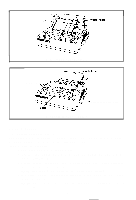
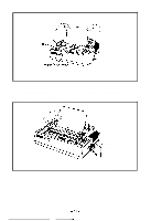
Fig. 41 Alignment of Side Edges, Fig. 42 Form Position Setting Mark, Fig. 43 Print Area
 |
View all Epson MX-82 F/T manuals
Add to My Manuals
Save this manual to your list of manuals |
Page 38 highlights
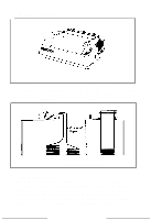
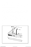
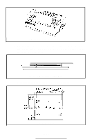
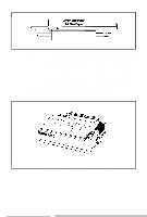
Fig. 41 Alignment of Side Edges b) If the cut paper sheet or form is not long enough to align the side edges, align the top edge of the paper with the form position setting mark on the tractor unit. (See Fig. 42) Fig. 42 Form Position Setting Mark The print area on the cut paper sheet is shown in Fig. 43. 210 mm (8.3")-218 mm f8.5") m5-8 5-8 mm 1! 28.6 or 30.2 mm, :CcD"EsE"~. 012 212334 305 mm (' 2"]J7:q Fig. 43 Print Area -32-
-
 1
1 -
2
-
3
-
4
-
5
-
6
-
7
-
8
-
9
-
10
-
11
-
12
-
13
-
14
-
15
-
16
-
17
-
18
-
19
-
20
-
21
-
22
-
23
-
24
-
25
-
26
-
27
-
28
-
29
-
30
-
31
-
32
-
 33
33 -
 34
34 -
 35
35 -
 36
36 -
 37
37 -
 38
38 -
 39
39 -
 40
40 -
 41
41 -
 42
42 -
 43
43 -
44
-
45
-
46
-
47
-
48
-
49
-
50
-
51
-
52
-
53
-
54
-
55
-
56
-
57
-
58
-
59
-
60
-
61
-
62
-
63
-
64
-
65
-
66
-
67
-
68
-
69
-
70
-
71
-
72
-
73
-
74
-
75
-
76
-
77
-
78
-
79
-
80
-
81
-
82
-
83
-
84
-
85
-
86
-
87
-
88
-
89
-
90
-
91
-
92
-
93
-
94
-
95
-
96
-
97
-
98
-
99
-
100
-
101
-
102
-
103
 |
 |
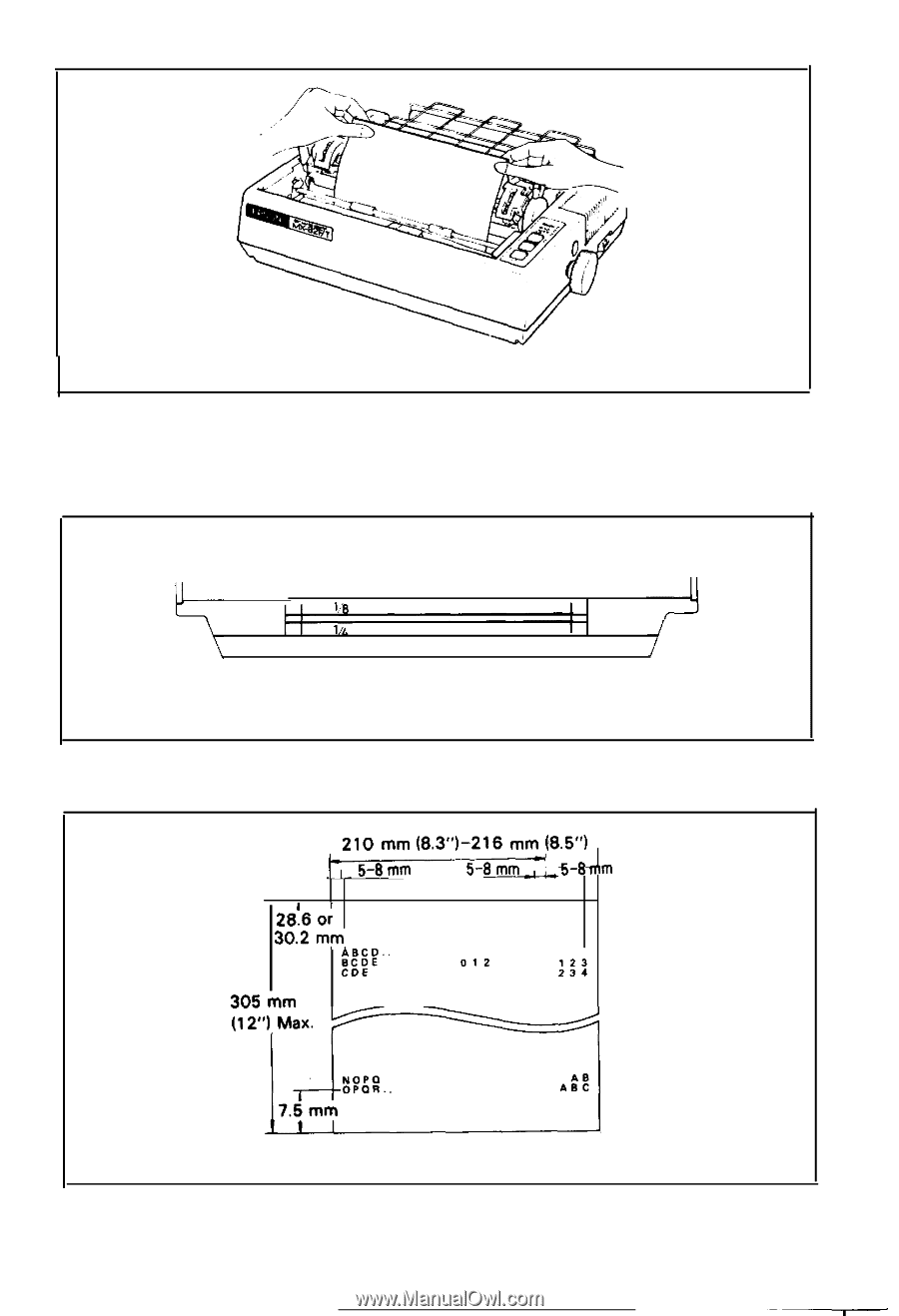
Fig. 41 Alignment of Side Edges
b) If the cut paper sheet or form is not long enough to align the side edges,
align the
top
edge of the paper with the form position setting mark on
the tractor unit. (See Fig. 42)
Fig. 42 Form Position Setting Mark
The print area on the cut paper sheet is shown in Fig. 43.
210
mm
(8.3”)-218
mm
f8.5”)
m5-8
5-8
mm
1
!
28.6
or
30.2
mm,
:c”sE”~.
012
123
CDE
234
305
mm
(’
2”]J7:q
Fig. 43 Print Area
-32-