Epson MX-82 F/T User Manual - Page 47
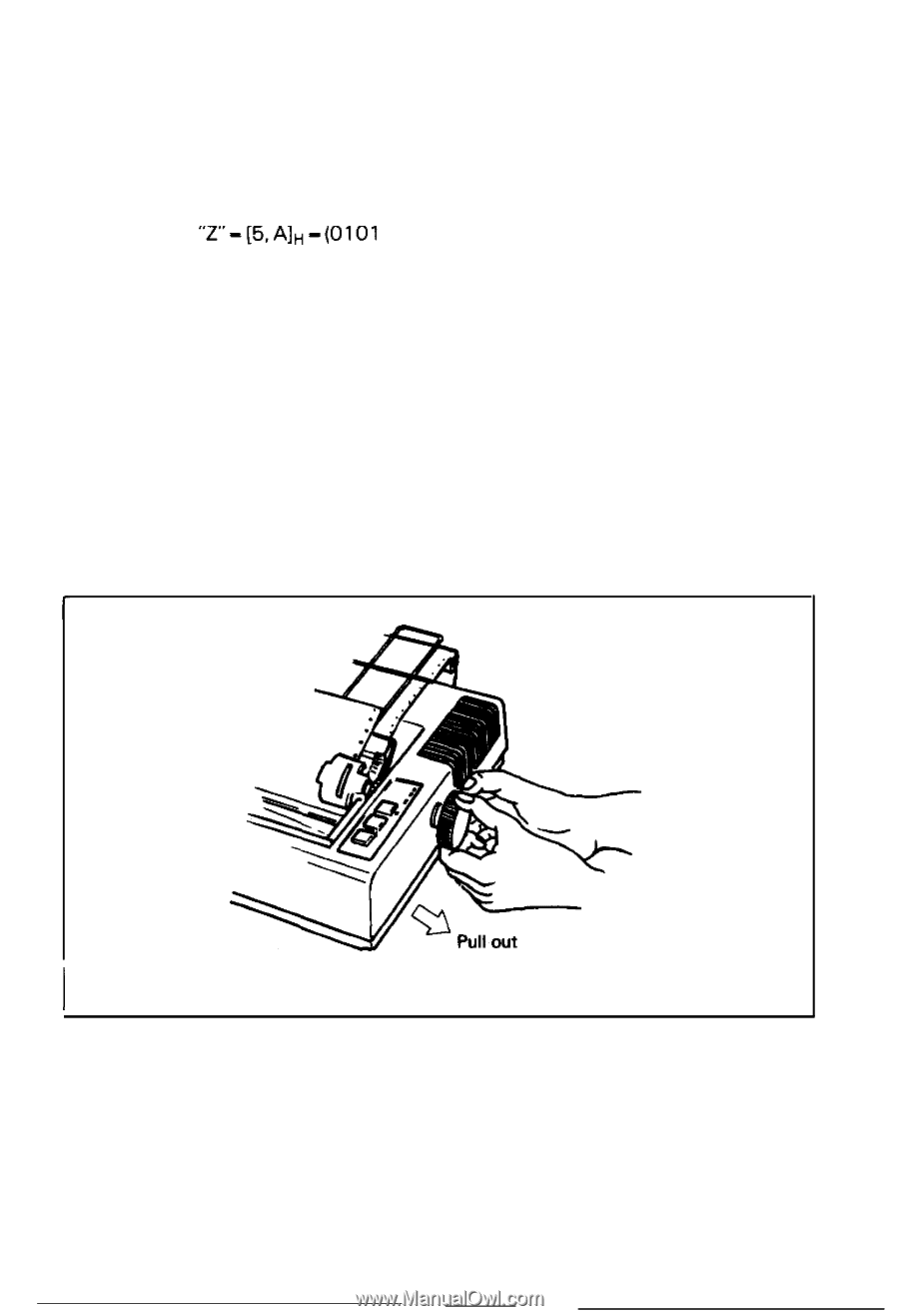
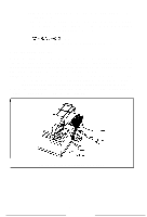
Setting of DIP Switches, Fig. 50 Removing
 |
View all Epson MX-82 F/T manuals
Add to My Manuals
Save this manual to your list of manuals |
Page 47 highlights
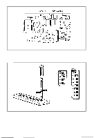
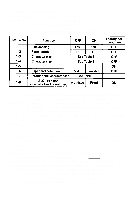
b) Turn the DIP switch 2-3 (on the control circuit board) ON to effect auto-line feed. c) Set the adequate ASCII code data to be printed. To obtain low logic level signals, connect the data transfer line required for printing (pin Nos. 2 to 9) to GND level (pin No. 33, etc.) * Example of printing "Z" "Z"-[5,A]H-(0101 1010) In this case, connect pin Nos. 2, 4, 7 and 9 to pin No. 33. 5. Setting of DIP Switches In order to suit the user's specific requirements, desired control modes are selectable by the two built-ion DIP switches. The DIP switches (SW1 and SW2) located on the control circuit board of the Printer are as shown in Fig. 54. To gain access to the DIP switches, the upper case of the Printer must be removed. NOTE: Turn the power off whenever you attempt to open up the printer case. Ad- equately discharge static electricity which might be charged in your body, or it may cause damages to internal electronic parts such as LSl's, IC's, etc. Remove the manual paper feed knob (black knob on the right side) by pulling it straight out, with firm but steady force. (See Fig. 50) Fig. 50 Removing Manual Paper Feed Knob -41-
-
 1
1 -
2
-
3
-
4
-
5
-
6
-
7
-
8
-
9
-
10
-
11
-
12
-
13
-
14
-
15
-
16
-
17
-
18
-
19
-
20
-
21
-
22
-
23
-
24
-
25
-
26
-
27
-
28
-
29
-
30
-
31
-
32
-
33
-
34
-
35
-
36
-
37
-
38
-
39
-
40
-
41
-
 42
42 -
 43
43 -
 44
44 -
 45
45 -
 46
46 -
 47
47 -
 48
48 -
 49
49 -
 50
50 -
 51
51 -
 52
52 -
53
-
54
-
55
-
56
-
57
-
58
-
59
-
60
-
61
-
62
-
63
-
64
-
65
-
66
-
67
-
68
-
69
-
70
-
71
-
72
-
73
-
74
-
75
-
76
-
77
-
78
-
79
-
80
-
81
-
82
-
83
-
84
-
85
-
86
-
87
-
88
-
89
-
90
-
91
-
92
-
93
-
94
-
95
-
96
-
97
-
98
-
99
-
100
-
101
-
102
-
103
 |
 |