Epson MX-82 F/T User Manual - Page 90
Power circuit, Printer initialization, interrupted and reapplied i.e.
 |
View all Epson MX-82 F/T manuals
Add to My Manuals
Save this manual to your list of manuals |
Page 90 highlights
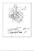
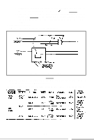
1.3 Power circuit The power circuit generates 5V DC for the logic circuit, and 24V DC to energize the solenoids of the print head and two stepper motors. 1.4 Printer initialization Printer initialization is accomplished in either of the two ways described below. (1) initialization takes place automatically each time the primary AC power source is interrupted and reapplied (i.e., by turning the Power Switch off and on). (2) Initialization may be initiated remotely by activating the INIT signal to the parallel intmfara rnnnartnr Thic Iinn chmnlrl ha A&cm hw a Tfl r&war nr it= ~n~~i~alant
-
 1
1 -
2
-
3
-
4
-
5
-
6
-
7
-
8
-
9
-
10
-
11
-
12
-
13
-
14
-
15
-
16
-
17
-
18
-
19
-
20
-
21
-
22
-
23
-
24
-
25
-
26
-
27
-
28
-
29
-
30
-
31
-
32
-
33
-
34
-
35
-
36
-
37
-
38
-
39
-
40
-
41
-
42
-
43
-
44
-
45
-
46
-
47
-
48
-
49
-
50
-
51
-
52
-
53
-
54
-
55
-
56
-
57
-
58
-
59
-
60
-
61
-
62
-
63
-
64
-
65
-
66
-
67
-
68
-
69
-
70
-
71
-
72
-
73
-
74
-
75
-
76
-
77
-
78
-
79
-
80
-
81
-
82
-
83
-
84
-
 85
85 -
 86
86 -
 87
87 -
 88
88 -
 89
89 -
 90
90 -
 91
91 -
 92
92 -
 93
93 -
 94
94 -
 95
95 -
96
-
97
-
98
-
99
-
100
-
101
-
102
-
103
 |
 |

1.3 Power circuit
The power circuit generates 5V DC for the logic circuit, and 24V DC to energize the
solenoids of the print head and two stepper motors.
1.4 Printer initialization
Printer initialization is accomplished in either of the two ways described below.
(1) initialization takes place automatically each time the primary AC power source is
interrupted and reapplied (i.e., by turning the Power Switch off and on).
(2) Initialization may be initiated remotely by activating the INIT signal to the parallel
intmfara
rnnnartnr
Thic
Iinn
chmnlrl
ha
A&cm
hw
a
Tfl
r&war
nr
it=
~n~~i~alant