Epson MX-82 F/T User Manual - Page 94
Fig. A2-1 shows the sequence for data transmission., Relations among the ON LINE switch
 |
View all Epson MX-82 F/T manuals
Add to My Manuals
Save this manual to your list of manuals |
Page 94 highlights
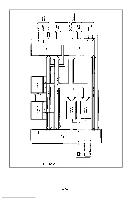
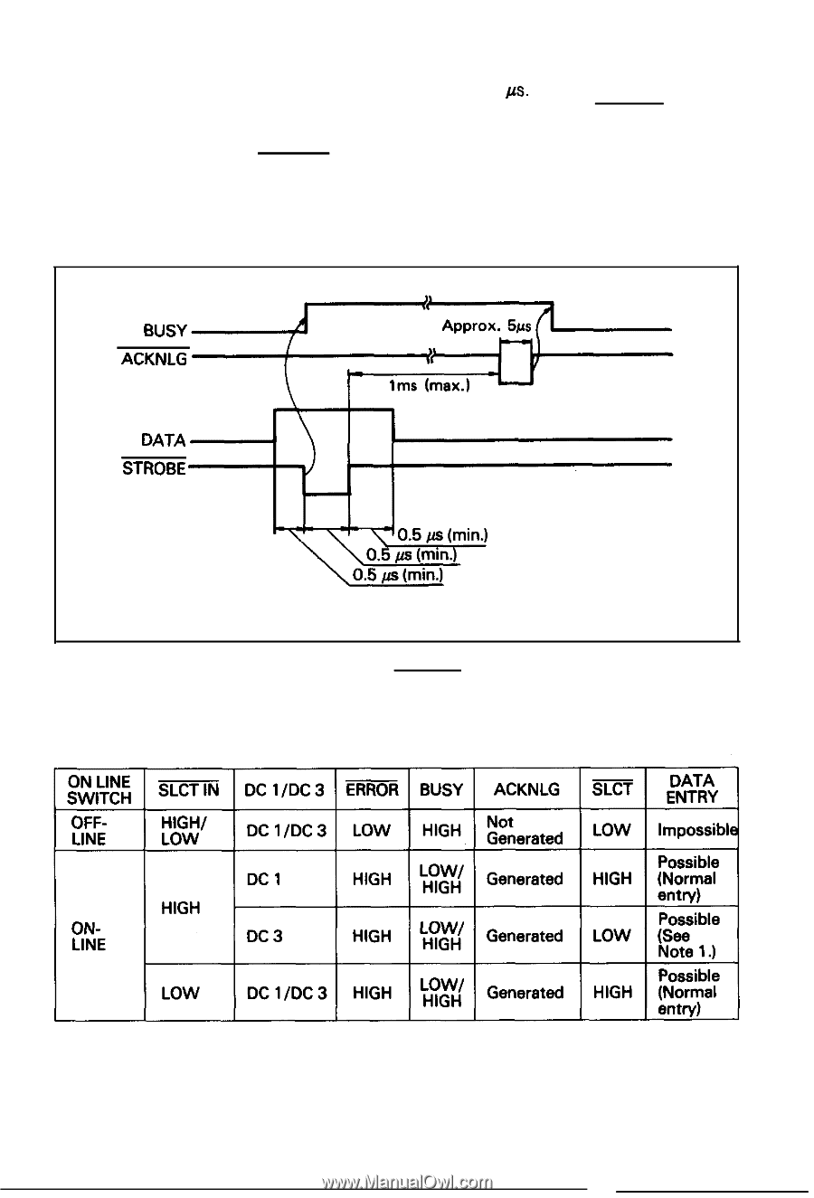
3. All interface conditions are based on TTL level. Both the rise and fall times of each signal must be less than 0.2 p.s. 4. Data transfer must not be carried out by ignoring the ACKNLG or BUSY signal. (Data transfer to this printer can be carried out only after confirming the ACKNLG signal or when the level of the BUSY signal is "LOW'.) (4) Data transfer sequence Fig. A2-1 shows the sequence for data transmission. BUSY ACKNLG DATA STROBE Fig. A2-1 Parallel Interface Timing Relations among the ON LINE switch, SLCT IN signal, DC l/DC 3 code and interface signals are shown in Table A2-2 below. Table A2-2 Relations among ON:LINE. SLCT IN, DC1 /DC3 and Interface Signal -89-
-
 1
1 -
2
-
3
-
4
-
5
-
6
-
7
-
8
-
9
-
10
-
11
-
12
-
13
-
14
-
15
-
16
-
17
-
18
-
19
-
20
-
21
-
22
-
23
-
24
-
25
-
26
-
27
-
28
-
29
-
30
-
31
-
32
-
33
-
34
-
35
-
36
-
37
-
38
-
39
-
40
-
41
-
42
-
43
-
44
-
45
-
46
-
47
-
48
-
49
-
50
-
51
-
52
-
53
-
54
-
55
-
56
-
57
-
58
-
59
-
60
-
61
-
62
-
63
-
64
-
65
-
66
-
67
-
68
-
69
-
70
-
71
-
72
-
73
-
74
-
75
-
76
-
77
-
78
-
79
-
80
-
81
-
82
-
83
-
84
-
85
-
86
-
87
-
88
-
 89
89 -
 90
90 -
 91
91 -
 92
92 -
 93
93 -
 94
94 -
 95
95 -
 96
96 -
 97
97 -
 98
98 -
 99
99 -
100
-
101
-
102
-
103
 |
 |
3. All interface conditions are based on TTL level. Both the rise and fall
times of each signal must be less than 0.2
p.s.
4. Data transfer must not be carried out by ignoring the ACKNLG or BUSY
signal. (Data transfer to this printer can be carried out only after con-
firming the ACKNLG signal or when the level of the BUSY signal is
“LOW’.)
(4) Data transfer sequence
Fig. A2-1 shows the sequence for data transmission.
BUSY
ACKNLG
DATA
STROBE
Fig. A2-1 Parallel Interface Timing
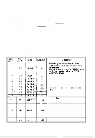
Relations among the ON LINE switch, SLCT IN signal, DC l/DC 3 code and inter-
face signals are shown in Table A2-2 below.
Table A2-2 Relations among ON:LINE. SLCT IN, DC1 /DC3 and Interface Signal
-89-