Epson MX-82 F/T User Manual - Page 52
Setting of DIP Switch No. 2, Table 4 Functions and Conditions of DIP Switch No. 2
 |
View all Epson MX-82 F/T manuals
Add to My Manuals
Save this manual to your list of manuals |
Page 52 highlights
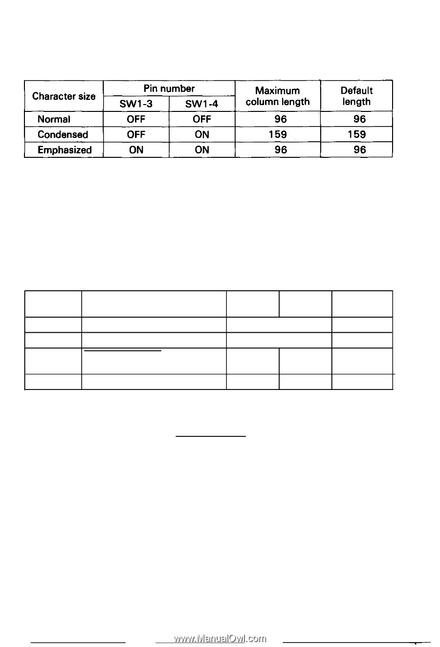
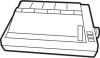
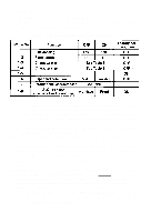
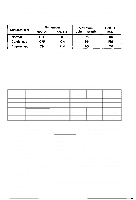
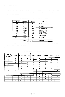
(8) Character sizes and maximum column lengths can be specified as follows: Table 3 Character Size and Maximum Column Length ~~ If you turn any of the above character sizes to the enlarged character print mode, then the maximum column length will be reduce to half of them. 5.2 Setting of DIP Switch No. 2 The DIP switch No. 2 consists of the following 4 pins. A summary of the functions of the respective DIP switch pins and their preset conditions at the time of shipment are shown in Table 4. Table 4 Functions and Conditions of DIP Switch No. 2 SW Pin No. Function 2-1 International character set 2-2 International character set 2-3 AUTO FEED XT signal internally fixed or not fixed 2-4 1 inch skip-over perforation OFF ON See Table 5. See Table 5. Not fixed Fixed Valid Invalid Factory-set Condition OFF ON (1) SW2-1 & 2-2: Combined use of these two pins and SW1 -7 permit selection of the international character set for U.S.A., France, Germany, England, Denmark, Sweden, Italy, and Spain as shown in Table 5 upon power application. (2) SW2-3: This pin is used to fix AUTO FEED XT signal internally. (Refer to the explanation of control code "CR" in paragraph 3.1 (1) "WHAT IS THE MX-82") This signal line is wired ORed with the pin No. 14 of the interface connector. Therefore, to control the pin No. 14 externally through TTL, etc., leave this DIP switch pin to the OFF position, (3) SW2-4: This pin is used to set the automatic skip-over perforation function. (a) When this pin is set to the OFF position, the automatic skip-over perforation function becomes valid. By this function, the paper automatically advances to the first line of the next page when the remaining page length is 1 inch. (b) When this pin is set to the ON position, the 1 inch automatic skip-over perforation function becomes invalid. However, you can activate this function programmably. (described in detail later.) -46-
-
 1
1 -
2
-
3
-
4
-
5
-
6
-
7
-
8
-
9
-
10
-
11
-
12
-
13
-
14
-
15
-
16
-
17
-
18
-
19
-
20
-
21
-
22
-
23
-
24
-
25
-
26
-
27
-
28
-
29
-
30
-
31
-
32
-
33
-
34
-
35
-
36
-
37
-
38
-
39
-
40
-
41
-
42
-
43
-
44
-
45
-
46
-
 47
47 -
 48
48 -
 49
49 -
 50
50 -
 51
51 -
 52
52 -
 53
53 -
 54
54 -
 55
55 -
 56
56 -
 57
57 -
58
-
59
-
60
-
61
-
62
-
63
-
64
-
65
-
66
-
67
-
68
-
69
-
70
-
71
-
72
-
73
-
74
-
75
-
76
-
77
-
78
-
79
-
80
-
81
-
82
-
83
-
84
-
85
-
86
-
87
-
88
-
89
-
90
-
91
-
92
-
93
-
94
-
95
-
96
-
97
-
98
-
99
-
100
-
101
-
102
-
103
 |
 |