Foxconn P35AP-S English manual. - Page 14
After installing the CPU, remove the protective cover from load plate.
 |
View all Foxconn P35AP-S manuals
Add to My Manuals
Save this manual to your list of manuals |
Page 14 highlights
Chapter 2 Installation Instructions 3. Hold CPU with thumb and forefinger. Ensure fingers align to socket cutouts. Match the CPU triangle marker to Pin 1 position as shown below. The alignment key also provides the orientation directed function. Lower the CPU straight down without tilting or sliding the CPU in the socket. Alignment Key Pin 1 position Socket Cutouts 4. After installing the CPU, remove the protective cover from load plate. The protective cover is used to protect the contacts of the socket. Do not discard the protective cover. Always replace the socket cover if the CPU is removed from the socket. 8
-
 1
1 -
2
-
3
-
4
-
5
-
6
-
7
-
8
-
 9
9 -
 10
10 -
 11
11 -
 12
12 -
 13
13 -
 14
14 -
 15
15 -
 16
16 -
 17
17 -
 18
18 -
 19
19 -
20
-
21
-
22
-
23
-
24
-
25
-
26
-
27
-
28
-
29
-
30
-
31
-
32
-
33
-
34
-
35
-
36
-
37
-
38
-
39
-
40
-
41
-
42
-
43
-
44
-
45
-
46
-
47
-
48
-
49
-
50
-
51
-
52
-
53
-
54
-
55
-
56
-
57
-
58
-
59
-
60
-
61
-
62
-
63
-
64
-
65
-
66
-
67
 |
 |
Chapter 2
Installation Instructions
8
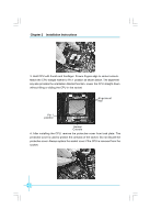
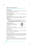
3. Hold CPU with thumb and forefinger. Ensure fingers align to socket cutouts.
Match the CPU triangle marker to Pin 1 position as shown below. The alignment
key also provides the orientation directed function. Lower the CPU straight down
without tilting or sliding the CPU in the socket.
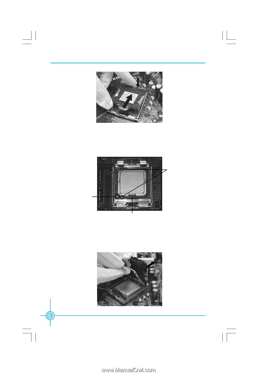
4. After installing the CPU, remove the protective cover from load plate. The
protective cover is used to protect the contacts of the socket. Do not discard the
protective cover. Always replace the socket cover if the CPU is removed from the
socket.
Alignment
Key
Socket
Cutouts
Pin 1
position