Foxconn P35AP-S English manual. - Page 19
Connector: F 1394Optional, USB Connectors: F_USB1/2, Fan Connectors: CPU_FAN,SYS_FAN,FAN1, NB _FAN,
 |
View all Foxconn P35AP-S manuals
Add to My Manuals
Save this manual to your list of manuals |
Page 19 highlights
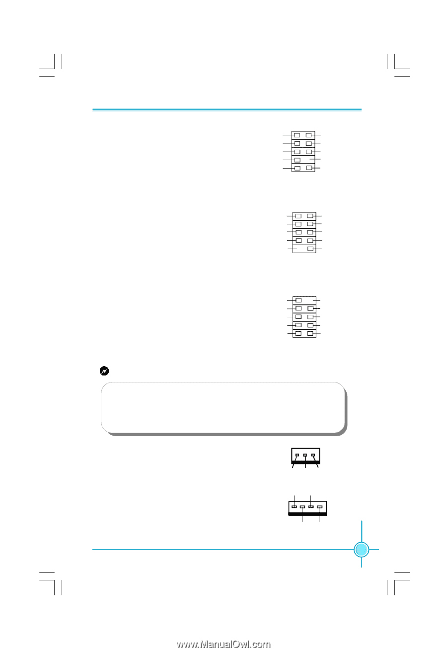
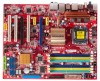
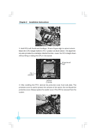
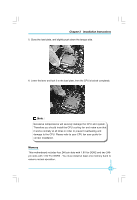
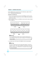
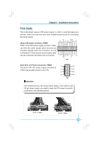
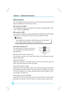
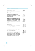
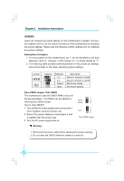
Chapter 2 Installation Instructions Audio Connector: F_AUDIO The audio connector supports HD audio PORT1_L PORT1_R 1 2 AUD_GND PRESENCEJ standard. It provides two kinds of audio output PORT2_R choices: the Front Audio, the Rear Audio. SENSE_SEND PORT2_L SENSE1_RETURN Empty SENSE2_RETURN 9 10 F_AUDIO (HDA) 1394 Connector: F 1394(Optional) The 1394 expansion cable can be connected to either the front (provided that the front panel of your chassis is equipped with the appropriate interface) or real panel of the chassis. TPA+ GND TPB+ +12V Empty 1 2 9 10 F 1394 TPAGND TPB+12V GND USB Connectors: F_USB1/2 In addition to the four USB ports on the rear panel,the series of motherboards also have two 10-pin connectors on board which may connect to the front panel USB cable to provide additional four USB ports. 10 9 NC Empty GND GND D+ D+ D- D- VCC VCC 2 1 F_USB1/2 Warning: Before installing the USB cables, please pay attention to the marker of each individual USB cable; make sure to match them with each USB pin headers correctly, otherwise the USB ports will not work. Incorrect connection could also damage the motherboard. Fan Connectors: CPU_FAN,SYS_FAN,FAN1/ 2,NB _FAN There are five fan connectors on this motherboard.The fan speed can be detected and viewed in "PC Health Status" section of the CMOS Setup. These fans will be automatically turned off after the system enters S3, S4 and S5 mode. 1 GND +12V SENSE FAN1/2,NB-FAN GND SENSE 1 POWER CONTROL CPU_FAN,SYS_FAN 13
-
 1
1 -
2
-
3
-
4
-
5
-
6
-
7
-
8
-
9
-
10
-
11
-
12
-
13
-
 14
14 -
 15
15 -
 16
16 -
 17
17 -
 18
18 -
 19
19 -
 20
20 -
 21
21 -
 22
22 -
 23
23 -
 24
24 -
25
-
26
-
27
-
28
-
29
-
30
-
31
-
32
-
33
-
34
-
35
-
36
-
37
-
38
-
39
-
40
-
41
-
42
-
43
-
44
-
45
-
46
-
47
-
48
-
49
-
50
-
51
-
52
-
53
-
54
-
55
-
56
-
57
-
58
-
59
-
60
-
61
-
62
-
63
-
64
-
65
-
66
-
67
 |
 |