Foxconn P35AP-S English manual. - Page 18
Other Connectors
 |
View all Foxconn P35AP-S manuals
Add to My Manuals
Save this manual to your list of manuals |
Page 18 highlights
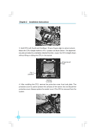
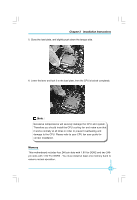
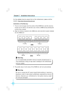
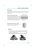
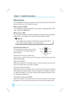
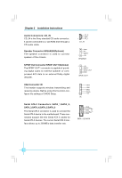
Chapter 2 Installation Instructions Other Connectors This motherboard includes connectors for FDD device, IDE device,Serial ATA devices, USB devices, IR module and others. FDD Connector: FLOPPY This motherboard includes a standard FDD connector, supporting 360K, 720K, 1.2M, 1.44M, and 2.88M FDDs. IDE Connectors: PIDE This connector support the provided Ultra DMA133/100/66 IDE hard disk ribbon cable and you can configure as a disk array through RAID controller. Attention: If you install only one device on the IDE port such as a hard disk or a CD _ROM, please configure it as a master device. Front Panel Connector: FP1 1 2 + + - This motherboard includes one connector HDD_LED PLED for connecting the front panel switch and LED indicators. RESET NC 9 PWRSW Empty 10 Hard Disk LED Connector (HDD-LED) FP1! The connector connects to the case's IDE indicator LED indicating the activity status of hard disks. Reset Switch (RESET) Attach the connector to the Reset switch on the front panel of the case; the system will restart when the switch is pressed. Power LED Connector (PLED) Attach the connector to the power LED on the front panel of the case. The Power LED indicates the system's status. W hen the system is in S0 status, the LED is on. When the system is in S1 status, the LED is blink; W hen the system is in S3, S4, S5 status, the LED is off. Power Switch Connector (PWRSW) Attach the connector to the power button of the case. Pushing this switch allows the system to be turned on and off rather than using the power supply button. 12
-
 1
1 -
2
-
3
-
4
-
5
-
6
-
7
-
8
-
9
-
10
-
11
-
12
-
 13
13 -
 14
14 -
 15
15 -
 16
16 -
 17
17 -
 18
18 -
 19
19 -
 20
20 -
 21
21 -
 22
22 -
 23
23 -
24
-
25
-
26
-
27
-
28
-
29
-
30
-
31
-
32
-
33
-
34
-
35
-
36
-
37
-
38
-
39
-
40
-
41
-
42
-
43
-
44
-
45
-
46
-
47
-
48
-
49
-
50
-
51
-
52
-
53
-
54
-
55
-
56
-
57
-
58
-
59
-
60
-
61
-
62
-
63
-
64
-
65
-
66
-
67
 |
 |
