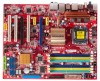
Foxconn P35AP-S English manual. - Page 22
Jumpers - user manual
 |
View all Foxconn P35AP-S manuals
Add to My Manuals
Save this manual to your list of manuals |
Page 22 highlights
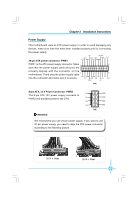
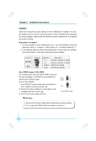
Chapter 2 Installation Instructions Jumpers Users can change the jumper settings on this motherboard if needed. This section explains how to use the various functions of this motherboard by changing the jumper settings. Please read the following content carefully prior to modifying any jumper settings. Description of Jumpers 1. For the jumpers on this motherboard, pin 1 can be identified by the bold silkscreen next to it. However, in this manual, pin 1 is simply labeled as "1". 2. The following table provides some explanation of the jumper pin settings. User should refer to this when adjusting jumper settings. Jumper 1 1 Diagram 1 1 1 1 Definition 1-2 2-3 Closed Open Description Set pin 1 and pin 2 closed Set pin 2 and pin 3 closed Set the pin closed Set the pin opened Clear CMOS Jumper: CLR_CMOS The motherboard uses the CMOS RAM to store all the set parameters. The CMOS can be cleared by removing the CMOS jumper. How to clear CMOS? 1. Turn off the AC power supply and connect pins 1 and 2 together using the jumper cap. 2. Return the jumper setting to normal (pins 2 and 3 together with the jumper cap). 3. Turn the AC power supply back on. Warning: 1 Normal 2 (default) 3 1 Clear 2 3 Clear CMOS Jumper 1. Disconnect the power cable before adjusting the jumper settings. 2. Do not clear the CMOS while the system is turned on. 16
-
 1
1 -
2
-
3
-
4
-
5
-
6
-
7
-
8
-
9
-
10
-
11
-
12
-
13
-
14
-
15
-
16
-
 17
17 -
 18
18 -
 19
19 -
 20
20 -
 21
21 -
 22
22 -
 23
23 -
 24
24 -
 25
25 -
 26
26 -
 27
27 -
28
-
29
-
30
-
31
-
32
-
33
-
34
-
35
-
36
-
37
-
38
-
39
-
40
-
41
-
42
-
43
-
44
-
45
-
46
-
47
-
48
-
49
-
50
-
51
-
52
-
53
-
54
-
55
-
56
-
57
-
58
-
59
-
60
-
61
-
62
-
63
-
64
-
65
-
66
-
67
 |
 |
