HP 2300d Service Manual - Page 155
Engine controller PCA, drive assembly
 |
UPC - 808736471091
View all HP 2300d manuals
Add to My Manuals
Save this manual to your list of manuals |
Page 155 highlights
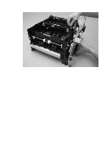
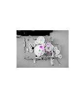
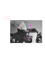
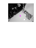
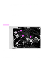
Note Engine controller PCA 1 Remove the following covers and assemblies: • I/O cover (see page 113) • DIMM cover (page 115) • rear cover (page 116) • front cover (page 119) • control panel (page 120) • top cover assembly (page 121) • formatter (page 147) • drive assembly (page 148) 2 Use a flatblade screwdriver to pry one connector (callout 1) off of the switch (callout 2). After the connector and the switch are separated, the switch can easily fall out of its place in the printer frame. Make sure that you do not lose the switch. 12 2 Figure 78. Removing the engine controller PCA (1 of 5) ENWW Chapter 6 Removal and replacement 153
-
 1
1 -
2
-
3
-
4
-
5
-
6
-
7
-
8
-
9
-
10
-
11
-
12
-
13
-
14
-
15
-
16
-
17
-
18
-
19
-
20
-
21
-
22
-
23
-
24
-
25
-
26
-
27
-
28
-
29
-
30
-
31
-
32
-
33
-
34
-
35
-
36
-
37
-
38
-
39
-
40
-
41
-
42
-
43
-
44
-
45
-
46
-
47
-
48
-
49
-
50
-
51
-
52
-
53
-
54
-
55
-
56
-
57
-
58
-
59
-
60
-
61
-
62
-
63
-
64
-
65
-
66
-
67
-
68
-
69
-
70
-
71
-
72
-
73
-
74
-
75
-
76
-
77
-
78
-
79
-
80
-
81
-
82
-
83
-
84
-
85
-
86
-
87
-
88
-
89
-
90
-
91
-
92
-
93
-
94
-
95
-
96
-
97
-
98
-
99
-
100
-
101
-
102
-
103
-
104
-
105
-
106
-
107
-
108
-
109
-
110
-
111
-
112
-
113
-
114
-
115
-
116
-
117
-
118
-
119
-
120
-
121
-
122
-
123
-
124
-
125
-
126
-
127
-
128
-
129
-
130
-
131
-
132
-
133
-
134
-
135
-
136
-
137
-
138
-
139
-
140
-
141
-
142
-
143
-
144
-
145
-
146
-
147
-
148
-
149
-
 150
150 -
 151
151 -
 152
152 -
 153
153 -
 154
154 -
 155
155 -
 156
156 -
 157
157 -
 158
158 -
 159
159 -
 160
160 -
161
-
162
-
163
-
164
-
165
-
166
-
167
-
168
-
169
-
170
-
171
-
172
-
173
-
174
-
175
-
176
-
177
-
178
-
179
-
180
-
181
-
182
-
183
-
184
-
185
-
186
-
187
-
188
-
189
-
190
-
191
-
192
-
193
-
194
-
195
-
196
-
197
-
198
-
199
-
200
-
201
-
202
-
203
-
204
-
205
-
206
-
207
-
208
-
209
-
210
-
211
-
212
-
213
-
214
-
215
-
216
-
217
-
218
-
219
-
220
-
221
-
222
-
223
-
224
-
225
-
226
-
227
-
228
-
229
-
230
-
231
-
232
-
233
-
234
-
235
-
236
-
237
-
238
-
239
-
240
-
241
-
242
-
243
-
244
-
245
-
246
-
247
-
248
-
249
-
250
-
251
-
252
-
253
-
254
-
255
-
256
-
257
-
258
-
259
-
260
-
261
-
262
-
263
-
264
-
265
-
266
-
267
-
268
-
269
-
270
-
271
-
272
-
273
-
274
-
275
-
276
-
277
-
278
-
279
-
280
-
281
-
282
-
283
-
284
-
285
-
286
-
287
-
288
-
289
-
290
-
291
-
292
-
293
-
294
-
295
-
296
 |
 |

ENWW
Chapter 6 Removal and replacement
153
Engine controller PCA
1
Remove the following covers and assemblies:
•
I/O cover (see page 113)
•
DIMM cover (page 115)
•
rear cover (page 116)
•
front cover (page 119)
•
control panel (page 120)
•
top cover assembly (page 121)
•
formatter (page 147)
•
drive assembly (page 148)
2
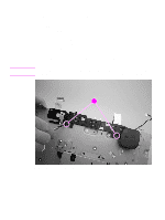
Use a flatblade screwdriver to pry one connector (callout 1) off of the switch (callout 2).
Note
After the connector and the switch are separated, the switch can easily fall out of its place in the
printer frame. Make sure that you do not lose the switch.
Figure 78.
Removing the engine controller PCA (1 of 5)
2
2
1
2