HP 2300d Service Manual - Page 160
Solenoid, Removing the solenoid
 |
UPC - 808736471091
View all HP 2300d manuals
Add to My Manuals
Save this manual to your list of manuals |
Page 160 highlights
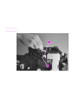
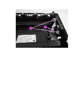
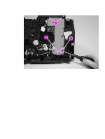
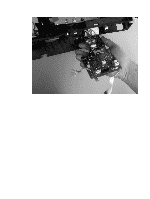
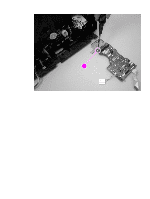
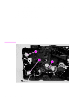
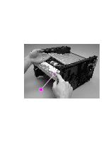
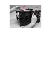
Note Solenoid The three solenoids can be removed by removing one screw from each solenoid. Figure 83 shows each of the solenoids: q tray 1 pickup solenoid (callout 1) q tray 2 pickup solenoid (callout 2) q automatic duplexer solenoid (callout 3) 1 Remove the following covers and assemblies: • I/O cover (see page 113) • DIMM cover (page 115) • rear cover (page 116) • front cover (page 119) • control panel (page 120) • top cover assembly (page 121) • formatter (page 147) • drive assembly (page 148) • engine controller PCA 2 Remove one screw and then lift the solenoid out of the printer. Pay close attention to the cable routing for the solenoid as you remove it. 12 2 12 32 Figure 83. Removing the solenoid 158 Removal and replacement 2 ENWW
-
 1
1 -
2
-
3
-
4
-
5
-
6
-
7
-
8
-
9
-
10
-
11
-
12
-
13
-
14
-
15
-
16
-
17
-
18
-
19
-
20
-
21
-
22
-
23
-
24
-
25
-
26
-
27
-
28
-
29
-
30
-
31
-
32
-
33
-
34
-
35
-
36
-
37
-
38
-
39
-
40
-
41
-
42
-
43
-
44
-
45
-
46
-
47
-
48
-
49
-
50
-
51
-
52
-
53
-
54
-
55
-
56
-
57
-
58
-
59
-
60
-
61
-
62
-
63
-
64
-
65
-
66
-
67
-
68
-
69
-
70
-
71
-
72
-
73
-
74
-
75
-
76
-
77
-
78
-
79
-
80
-
81
-
82
-
83
-
84
-
85
-
86
-
87
-
88
-
89
-
90
-
91
-
92
-
93
-
94
-
95
-
96
-
97
-
98
-
99
-
100
-
101
-
102
-
103
-
104
-
105
-
106
-
107
-
108
-
109
-
110
-
111
-
112
-
113
-
114
-
115
-
116
-
117
-
118
-
119
-
120
-
121
-
122
-
123
-
124
-
125
-
126
-
127
-
128
-
129
-
130
-
131
-
132
-
133
-
134
-
135
-
136
-
137
-
138
-
139
-
140
-
141
-
142
-
143
-
144
-
145
-
146
-
147
-
148
-
149
-
150
-
151
-
152
-
153
-
154
-
 155
155 -
 156
156 -
 157
157 -
 158
158 -
 159
159 -
 160
160 -
 161
161 -
 162
162 -
 163
163 -
 164
164 -
 165
165 -
166
-
167
-
168
-
169
-
170
-
171
-
172
-
173
-
174
-
175
-
176
-
177
-
178
-
179
-
180
-
181
-
182
-
183
-
184
-
185
-
186
-
187
-
188
-
189
-
190
-
191
-
192
-
193
-
194
-
195
-
196
-
197
-
198
-
199
-
200
-
201
-
202
-
203
-
204
-
205
-
206
-
207
-
208
-
209
-
210
-
211
-
212
-
213
-
214
-
215
-
216
-
217
-
218
-
219
-
220
-
221
-
222
-
223
-
224
-
225
-
226
-
227
-
228
-
229
-
230
-
231
-
232
-
233
-
234
-
235
-
236
-
237
-
238
-
239
-
240
-
241
-
242
-
243
-
244
-
245
-
246
-
247
-
248
-
249
-
250
-
251
-
252
-
253
-
254
-
255
-
256
-
257
-
258
-
259
-
260
-
261
-
262
-
263
-
264
-
265
-
266
-
267
-
268
-
269
-
270
-
271
-
272
-
273
-
274
-
275
-
276
-
277
-
278
-
279
-
280
-
281
-
282
-
283
-
284
-
285
-
286
-
287
-
288
-
289
-
290
-
291
-
292
-
293
-
294
-
295
-
296
 |
 |

158
Removal and replacement
ENWW
Solenoid
The three solenoids can be removed by removing one screw from each solenoid. Figure 83
shows each of the solenoids:
●
tray 1 pickup solenoid (callout 1)
●
tray 2 pickup solenoid (callout 2)
●
automatic duplexer solenoid (callout 3)
1
Remove the following covers and assemblies:
•
I/O cover (see page 113)
•
DIMM cover (page 115)
•
rear cover (page 116)
•
front cover (page 119)
•
control panel (page 120)
•
top cover assembly (page 121)
•
formatter (page 147)
•
drive assembly (page 148)
•
engine controller PCA
2
Remove one screw and then lift the solenoid out of the printer.
Note
Pay close attention to the cable routing for the solenoid as you remove it.
Figure 83.
Removing the solenoid
2
2
1
2
2
2
2
1
2
3