HP 6125XLG R2306-HP 6125XLG Blade Switch High Availability Configuration Guide - Page 124
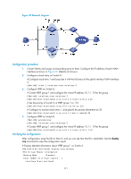
/24 through Switch C and Switch B., Display information about the track entry on Switch A.
 |
View all HP 6125XLG manuals
Add to My Manuals
Save this manual to your list of manuals |
Page 124 highlights
Destinations : 9 Destination/Mask Proto Pre 10.2.1.0/24 Direct 0 10.2.1.1/32 Direct 0 10.3.1.0/24 Direct 0 10.3.1.1/32 Direct 0 20.1.1.0/24 Direct 0 20.1.1.1/32 Direct 0 30.1.1.0/24 Static 60 127.0.0.0/8 Direct 0 127.0.0.1/32 Direct 0 Routes : 9 Cost 0 0 0 0 0 0 0 0 0 NextHop 10.2.1.1 127.0.0.1 10.3.1.1 127.0.0.1 20.1.1.1 127.0.0.1 10.2.1.2 127.0.0.1 127.0.0.1 Interface Vlan2 InLoop0 Vlan3 InLoop0 Vlan5 InLoop0 Vlan2 InLoop0 InLoop0 The output shows the BFD detection result: the next hop 10.2.1.2 is reachable (the status of the track entry is Positive). The master static route takes effect. Switch A forwards packets to 30.1.1.0/24 through Switch B. # Remove the IP address of interface VLAN-interface 2 on Switch B. system-view [SwitchB] interface vlan-interface 2 [SwitchB-Vlan-interface2] undo ip address # Display information about the track entry on Switch A. [SwitchA] display track all Track ID: 1 State: Negative Duration: 0 days 0 hours 0 minutes 32 seconds Notification delay: Positive 0, Negative 0 (in seconds) Tracked object: BFD session mode: Echo Outgoing interface: Vlan-interface2 VPN instance name: Remote IP: 10.2.1.2 Local IP: 10.2.1.1 # Display the routing table of Switch A. [SwitchA] display ip routing-table Routing Tables: Public Destinations : 9 Routes : 9 Destination/Mask Proto Pre Cost 10.2.1.0/24 Direct 0 0 10.2.1.1/32 Direct 0 0 10.3.1.0/24 Direct 0 0 10.3.1.1/32 Direct 0 0 20.1.1.0/24 Direct 0 0 20.1.1.1/32 Direct 0 0 30.1.1.0/24 Static 80 0 127.0.0.0/8 Direct 0 0 127.0.0.1/32 Direct 0 0 NextHop 10.2.1.1 127.0.0.1 10.3.1.1 127.0.0.1 20.1.1.1 127.0.0.1 10.3.1.3 127.0.0.1 127.0.0.1 Interface Vlan2 InLoop0 Vlan3 InLoop0 Vlan5 InLoop0 Vlan3 InLoop0 InLoop0 The output shows the BFD detection result: the next hop 10.2.1.2 is unreachable (the status of the track entry is Negative), and the backup static route takes effect, and Switch A forwards packets to 30.1.1.0/24 through Switch C and Switch B. 119
-
 1
1 -
2
-
3
-
4
-
5
-
6
-
7
-
8
-
9
-
10
-
11
-
12
-
13
-
14
-
15
-
16
-
17
-
18
-
19
-
20
-
21
-
22
-
23
-
24
-
25
-
26
-
27
-
28
-
29
-
30
-
31
-
32
-
33
-
34
-
35
-
36
-
37
-
38
-
39
-
40
-
41
-
42
-
43
-
44
-
45
-
46
-
47
-
48
-
49
-
50
-
51
-
52
-
53
-
54
-
55
-
56
-
57
-
58
-
59
-
60
-
61
-
62
-
63
-
64
-
65
-
66
-
67
-
68
-
69
-
70
-
71
-
72
-
73
-
74
-
75
-
76
-
77
-
78
-
79
-
80
-
81
-
82
-
83
-
84
-
85
-
86
-
87
-
88
-
89
-
90
-
91
-
92
-
93
-
94
-
95
-
96
-
97
-
98
-
99
-
100
-
101
-
102
-
103
-
104
-
105
-
106
-
107
-
108
-
109
-
110
-
111
-
112
-
113
-
114
-
115
-
116
-
117
-
118
-
 119
119 -
 120
120 -
 121
121 -
 122
122 -
 123
123 -
 124
124 -
 125
125 -
 126
126 -
 127
127 -
 128
128 -
 129
129 -
130
-
131
-
132
-
133
-
134
-
135
-
136
-
137
-
138
-
139
-
140
-
141
-
142
-
143
-
144
 |
 |
