HP 6125XLG R2306-HP 6125XLG Blade Switch High Availability Configuration Guide - Page 126
Configuration procedure, Verifying the configuration, Network diagram
 |
View all HP 6125XLG manuals
Add to My Manuals
Save this manual to your list of manuals |
Page 126 highlights
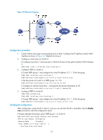
Figure 32 Network diagram Configuration procedure 1. Create VLANs and assign corresponding ports to them. Configure the IP address of each VLAN interface as shown in Figure 32. (Details not shown.) 2. Configure a track entry on Switch A: # Configure track entry 1 and associate it with the link status of the uplink interface VLAN-interface 3. [SwitchA] track 1 interface vlan-interface 3 3. Configure VRRP on Switch A: # Create VRRP group 1 and configure the virtual IP address 10.1.1.10 for the group. [SwitchA] interface vlan-interface 2 [SwitchA-Vlan-interface2] vrrp vrid 1 virtual-ip 10.1.1.10 # Set the priority of Switch A in VRRP group 1 to 110. [SwitchA-Vlan-interface2] vrrp vrid 1 priority 110 # Configure to monitor track entry 1, and specify the priority decrement as 30. [SwitchA-Vlan-interface2] vrrp vrid 1 track 1 reduced 30 4. Configure VRRP on Switch B: system-view [SwitchB] interface vlan-interface 2 # Create VRRP group 1 and configure the virtual IP address 10.1.1.10 for the group. [SwitchB-Vlan-interface2] vrrp vrid 1 virtual-ip 10.1.1.10 Verifying the configuration After configuration, ping Host B on Host A, and you can see that Host B is reachable. Use the display vrrp command to view the configuration result. # Display detailed information about VRRP group 1 on Switch A. [SwitchA-Vlan-interface2] display vrrp verbose IPv4 Virtual Router Information: Running Mode : Standard Total number of virtual routers : 1 Interface Vlan-interface2 121
-
 1
1 -
2
-
3
-
4
-
5
-
6
-
7
-
8
-
9
-
10
-
11
-
12
-
13
-
14
-
15
-
16
-
17
-
18
-
19
-
20
-
21
-
22
-
23
-
24
-
25
-
26
-
27
-
28
-
29
-
30
-
31
-
32
-
33
-
34
-
35
-
36
-
37
-
38
-
39
-
40
-
41
-
42
-
43
-
44
-
45
-
46
-
47
-
48
-
49
-
50
-
51
-
52
-
53
-
54
-
55
-
56
-
57
-
58
-
59
-
60
-
61
-
62
-
63
-
64
-
65
-
66
-
67
-
68
-
69
-
70
-
71
-
72
-
73
-
74
-
75
-
76
-
77
-
78
-
79
-
80
-
81
-
82
-
83
-
84
-
85
-
86
-
87
-
88
-
89
-
90
-
91
-
92
-
93
-
94
-
95
-
96
-
97
-
98
-
99
-
100
-
101
-
102
-
103
-
104
-
105
-
106
-
107
-
108
-
109
-
110
-
111
-
112
-
113
-
114
-
115
-
116
-
117
-
118
-
119
-
120
-
 121
121 -
 122
122 -
 123
123 -
 124
124 -
 125
125 -
 126
126 -
 127
127 -
 128
128 -
 129
129 -
 130
130 -
 131
131 -
132
-
133
-
134
-
135
-
136
-
137
-
138
-
139
-
140
-
141
-
142
-
143
-
144
 |
 |
