HP 6125XLG R2306-HP 6125XLG Blade Switch High Availability Configuration Guide - Page 16
Ethernet OAM configuration example, Network requirements, Configuration procedure
 |
View all HP 6125XLG manuals
Add to My Manuals
Save this manual to your list of manuals |
Page 16 highlights
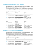
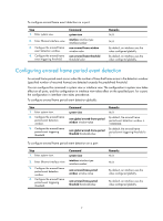
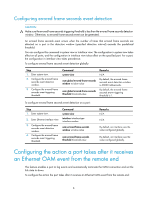
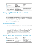
Purpose Command Display the statistics on Ethernet OAM link error events after an Ethernet OAM connection is established. display oam link-event { local | remote } [ interface interface-type interface-number ] Clear statistics on Ethernet OAM packets and Ethernet OAM link error events. reset oam [ interface interface-type interface-number ] Ethernet OAM configuration example Network requirements On the network shown in Figure 1, perform the following operations: • Enable Ethernet OAM on Device A and Device B to auto-detect link errors between the two devices • Determine the performance of the link between Device A and Device B by collecting statistics about the error frames received by Device A Figure 1 Network diagram Configuration procedure 1. Configure Device A: # Configure Ten-GigabitEthernet 1/1/5 to operate in active Ethernet OAM mode, and enable Ethernet OAM for it. system-view [DeviceA] interface ten-gigabitethernet 1/1/5 [DeviceA-Ten-GigabitEthernet1/1/5] oam mode active [DeviceA-Ten-GigabitEthernet1/1/5] oam enable # Set the errored frame event detection window to 20000 milliseconds, and set the errored frame event triggering threshold to 10. [DeviceA] oam errored-frame period 200 [DeviceA] oam errored-frame threshold 10 [DeviceA-Ten-GigabitEthernet1/1/5] quit 2. Configure Device B: # Configure Ten-GigabitEthernet 1/1/5 to operate in passive Ethernet OAM mode (the default), and enable Ethernet OAM for it. system-view [DeviceB] interface ten-gigabitethernet 1/1/5 [DeviceB-Ten-GigabitEthernet1/1/5] oam mode passive [DeviceB-Ten-GigabitEthernet1/1/5] oam enable [DeviceB-Ten-GigabitEthernet1/1/5] quit 3. Verify the configuration: 11
-
 1
1 -
2
-
3
-
4
-
5
-
6
-
7
-
8
-
9
-
10
-
 11
11 -
 12
12 -
 13
13 -
 14
14 -
 15
15 -
 16
16 -
 17
17 -
 18
18 -
 19
19 -
 20
20 -
 21
21 -
22
-
23
-
24
-
25
-
26
-
27
-
28
-
29
-
30
-
31
-
32
-
33
-
34
-
35
-
36
-
37
-
38
-
39
-
40
-
41
-
42
-
43
-
44
-
45
-
46
-
47
-
48
-
49
-
50
-
51
-
52
-
53
-
54
-
55
-
56
-
57
-
58
-
59
-
60
-
61
-
62
-
63
-
64
-
65
-
66
-
67
-
68
-
69
-
70
-
71
-
72
-
73
-
74
-
75
-
76
-
77
-
78
-
79
-
80
-
81
-
82
-
83
-
84
-
85
-
86
-
87
-
88
-
89
-
90
-
91
-
92
-
93
-
94
-
95
-
96
-
97
-
98
-
99
-
100
-
101
-
102
-
103
-
104
-
105
-
106
-
107
-
108
-
109
-
110
-
111
-
112
-
113
-
114
-
115
-
116
-
117
-
118
-
119
-
120
-
121
-
122
-
123
-
124
-
125
-
126
-
127
-
128
-
129
-
130
-
131
-
132
-
133
-
134
-
135
-
136
-
137
-
138
-
139
-
140
-
141
-
142
-
143
-
144
 |
 |
