HP OMEN Transcend 16 Maintenance and Service Guide - Page 39
Removal and replacement procedures for Customer Self-Repair parts, Component replacement procedures
 |
View all HP OMEN Transcend 16 manuals
Add to My Manuals
Save this manual to your list of manuals |
Page 39 highlights
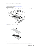
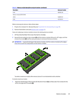
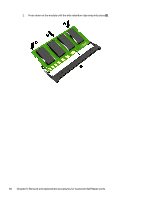
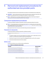
5 Removal and replacement procedures for Customer Self-Repair parts This chapter provides removal and replacement procedures for Customer Self-Repair parts. NOTE: The Customer Self-Repair program is not available in all locations. Installing a part that is not supported by the Customer Self-Repair program can void your warranty. Check your warranty to determine whether Customer Self-Repair is supported in your location. Component replacement procedures To remove and replace computer components, use these procedures. NOTE: Details about your computer, including model, serial number, product key, and length of warranty, are on the service tag at the bottom of your computer. NOTE: HP continually improves and changes product parts. For complete and current information about supported parts for your computer, go to http://partsurfer.hp.com, select your country or region, and then follow the on-screen instructions. Make special note of each screw size and location during removal and replacement. Preparation for disassembly To prepare to disassemble the computer, use these steps. See Removal and replacement procedures preliminary requirements on page 23 for initial safety procedures. 1. Turn off the computer. If you are unsure whether the computer is off or in Hibernation, turn the computer on, and then shut it down through the operating system. 2. Disconnect the power from the computer by unplugging the power cord from the computer. 3. Disconnect all external devices from the computer. Solid-state drive To remove the solid-state drive, use this procedure and illustration. Table 5-1 Solid-state drive descriptions and part numbers Description 2 TB 1 TB 512 GB Solid-state drive thermal pad Spare part number M52027-001 M16560-001 M17436-001 N15681-001 32 Chapter 5 Removal and replacement procedures for Customer Self-Repair parts
-
 1
1 -
2
-
3
-
4
-
5
-
6
-
7
-
8
-
9
-
10
-
11
-
12
-
13
-
14
-
15
-
16
-
17
-
18
-
19
-
20
-
21
-
22
-
23
-
24
-
25
-
26
-
27
-
28
-
29
-
30
-
31
-
32
-
33
-
 34
34 -
 35
35 -
 36
36 -
 37
37 -
 38
38 -
 39
39 -
 40
40 -
 41
41 -
 42
42 -
 43
43 -
 44
44 -
45
-
46
-
47
-
48
-
49
-
50
-
51
-
52
-
53
-
54
-
55
-
56
-
57
-
58
-
59
-
60
-
61
-
62
-
63
-
64
-
65
-
66
-
67
-
68
-
69
-
70
-
71
-
72
-
73
-
74
-
75
-
76
-
77
-
78
-
79
-
80
-
81
-
82
-
83
-
84
-
85
-
86
-
87
-
88
-
89
-
90
-
91
-
92
 |
 |
