HP OMEN Transcend 16 Maintenance and Service Guide - Page 50
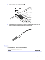
Touchpad, Remove the two broad head Phillips M2.0 × 2.0 screws
 |
View all HP OMEN Transcend 16 manuals
Add to My Manuals
Save this manual to your list of manuals |
Page 50 highlights
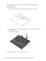
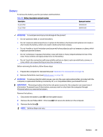
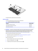
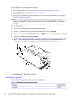
Table 6-5 Lighting board description and part number (continued) Description Lighting board LED per key cable Lighting board keyboard cable Spare part number N43721-001 N43720-001 Before removing the lighting board, follow these steps: 1. Prepare the computer for disassembly (see Preparation for disassembly on page 37). 2. Remove the bottom cover (see Bottom cover on page 37). 3. Remove the battery (see Battery on page 39). Remove the lighting board: NOTE: All flat cable connectors are covered with a piece of Mylar to prevent accidental disconnection. Be sure to replace this Mylar during reassembly. 1. Disconnect the four cables from the ZIF connectors on the board (1). 2. Remove the two broad head Phillips M2.0 × 2.0 screws (2) that secure the board to the computer. 3. Remove the board (3). To install the per key lighting board, reverse this procedure. Touchpad To remove the touchpad, use this procedure and illustration. Touchpad 43
-
 1
1 -
2
-
3
-
4
-
5
-
6
-
7
-
8
-
9
-
10
-
11
-
12
-
13
-
14
-
15
-
16
-
17
-
18
-
19
-
20
-
21
-
22
-
23
-
24
-
25
-
26
-
27
-
28
-
29
-
30
-
31
-
32
-
33
-
34
-
35
-
36
-
37
-
38
-
39
-
40
-
41
-
42
-
43
-
44
-
 45
45 -
 46
46 -
 47
47 -
 48
48 -
 49
49 -
 50
50 -
 51
51 -
 52
52 -
 53
53 -
 54
54 -
 55
55 -
56
-
57
-
58
-
59
-
60
-
61
-
62
-
63
-
64
-
65
-
66
-
67
-
68
-
69
-
70
-
71
-
72
-
73
-
74
-
75
-
76
-
77
-
78
-
79
-
80
-
81
-
82
-
83
-
84
-
85
-
86
-
87
-
88
-
89
-
90
-
91
-
92
 |
 |
