HP OmniBook 900 HP OmniBook 900 - Docking System User Guide - Page 49
Using the alternate installation procedure
 |
View all HP OmniBook 900 manuals
Add to My Manuals
Save this manual to your list of manuals |
Page 49 highlights
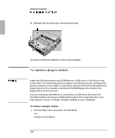
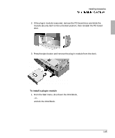
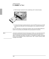
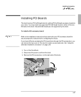
Installing Accessories 10. Connect any necessary external cables to the PCI board. 11. Reboot your Omnibook. You have completed installation of a PCI board. Using the alternate installation procedure If you have difficulty accessing the PCI board slots through the PCI access door, you can remove the top cover of the dock for easier access (optional). 1. Remove the top cover of the dock following steps 1 through 8 of "To install the module bay adapter" on page 1-40. 2. Remove the two screws securing the hinged section of the PCI board housing 3. Open the hinged section. 4. Do steps 1 through 8 of the previous procedure, "To install a PCI accessory board". 5. Close the hinged section of the PCI board housing and re-install the 2 screws. 1-49
-
 1
1 -
2
-
3
-
4
-
5
-
6
-
7
-
8
-
9
-
10
-
11
-
12
-
13
-
14
-
15
-
16
-
17
-
18
-
19
-
20
-
21
-
22
-
23
-
24
-
25
-
26
-
27
-
28
-
29
-
30
-
31
-
32
-
33
-
34
-
35
-
36
-
37
-
38
-
39
-
40
-
41
-
42
-
43
-
 44
44 -
 45
45 -
 46
46 -
 47
47 -
 48
48 -
 49
49 -
 50
50 -
 51
51 -
 52
52 -
 53
53 -
 54
54 -
55
-
56
-
57
-
58
-
59
-
60
-
61
-
62
-
63
-
64
-
65
-
66
-
67
-
68
-
69
-
70
-
71
-
72
-
73
-
74
-
75
-
76
 |
 |

Installing Accessories
1-49
10. Connect any necessary external cables to the PCI board.
11. Reboot your Omnibook.
You have completed installation of a PCI board.
Using the alternate installation procedure
If you have difficulty accessing the PCI board slots through the PCI access door, you
can remove the top cover of
the dock for easier access (optional).
8S±EZSMH±VMWO±SJ±IPIGXVMGEP±WLSGO²±VIQSZI±XLI±TS[IV±GSVH±JVSQ±XLI±TS[IV±SYXPIX
FIJSVI±VIQSZMRK±XLI±XST±GSZIV±SJ±XLI±HSGO³±%PWS±VIQSZI±ER]±RIX[SVO±GSRRIGXMSRW²
ERH±HMWGSRRIGX±ER]±I\XIVREP±HIZMGIW³±%P[E]W±VITPEGI±XLI±XST±GSZIV±SJ±XLI±HSGO
FIJSVI±XYVRMRK±XLI±HSGO±SR±EKEMR³
1. Remove the top cover of the dock following steps 1 through 8 of
“To install the
module bay adapter
”
on page 1-40.
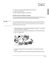
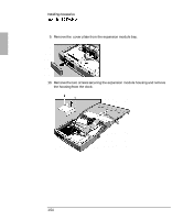
2. Remove the two screws securing the hinged section of the PCI board housing
3. Open the hinged section.
4. Do steps 1 through 8 of the previous procedure,
“To install a PCI accessory
board”.
5. Close the hinged section of the PCI board housing and re-install the 2 screws.